


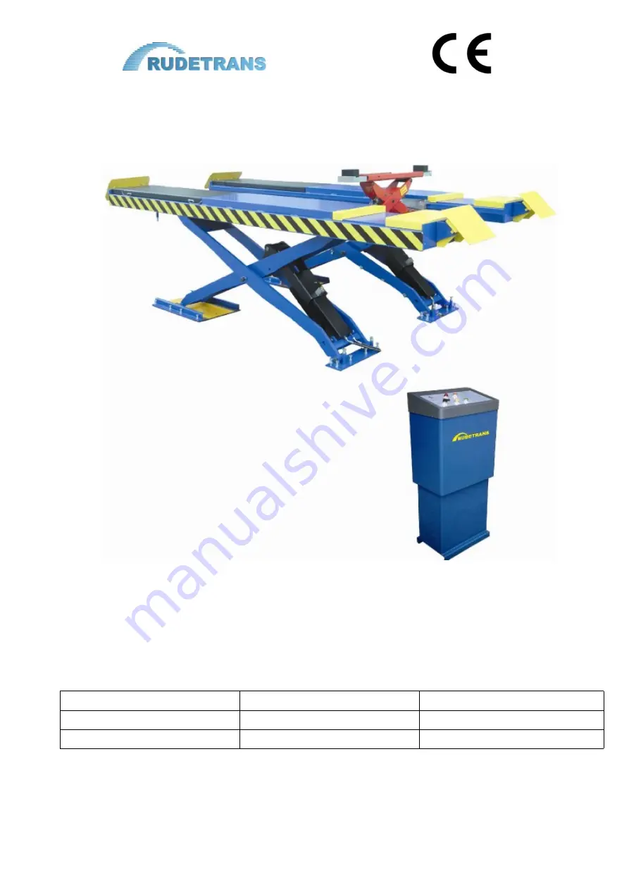
Large platform wheel alignment scissor lift
RLS-
4.5F
Ножничный подъёмник для сход-развала
RLS-4.5F
грузоподъёмностью 4,5т
USER'S MANUAL
РУКОВОДСТВО ПОЛЬЗОВАТЕЛЯ
Operating Manual & Instructions
Инструкции по эксплуатации и монтажу
Ref.№ 20091025
Русскоязычная версия:
25 апреля 2012
MODEL:
МОДЕЛЬ:
RLS-4.5F
Serial No.:
Серийный №:
Year of manufacture:
Год выпуска:


