RTD Alarm Setter Transmitter
□
FEATURES
:
:
:
:
Figure Display -100
~
400
℃
/-100
~
700
℉
Output / Set User Selectable
Ultrathin Type, 27mm Width
High Dielectric Strength ( AC 2KV/Min , between Input / Output / Power )
□
MODEL
:
:
:
:
TAR
INPUT
Setting Function
OUTPUT
AUX. POWER
A
Y
PT100
Ω
Ω
Ω
Ω
3Wire
-
100
~
~
~
~
400
℃
℃
℃
℃
/
-150
~
~
~
~
700
℉
℉
℉
℉
OTHER
A
B
C
N
Hi-Lo Setting
Hi-Hi Setting
Lo-Lo Setting
NONE
A
B
C
D
E
F
Y
DC 0~10mA
DC 0~20mA
DC 4~20mA
DC 0~5V
DC 1~5V
DC 0~10V
OTHER
C
F
Y
DC 24V
AC 85~265V
DC 100~300V
OTHER
□
SPECIFICATIONS
:
:
:
:
Accuracy
:
Input Accuracy ± 0.2
%
FS
、
Output Accuracy ± 0.1
%
RO
、
Display Accuracy ± 0.2
%
FS ±2C.
Display Range
:
0.28 High Lightness, Red LED 3 Digits. Under100, display decimal. Over100, display integer.
Input Impedance
:
Voltage Input
≧
1M
Ω
,
Current Input
≦
50
Ω
Insulation Resistance
:≧
100M
Ω
/ DC 500V
Output Load
:
DC Current Mode
:<
750
Ω
in Output 20mA
,
DC Voltage Mode
:
5mA Maximum
Output Coordination
:
Digit Coordination
Dielectric Strength
:
AC 2KV / 1Min
,
between Input / Output / Power. DIN IEC 688.
Setting Function
:
Two Units Alarm Joining. Hi / Lo User Selectable
Setting Range
:
0
~
800 Counts Adjustable
Nonmoving Zone
:
0
~
800 Counts Adjustable
Time Delay
:
0
~
999 sec Adjustable
Relay Contact
:
SPST AC 120V 5A ,250V 2.5A,DC 24V 3A PF=1
Stability
:
Year
≦
0.2
%
Response Time
:≦
1sec
Ripple
:≦
0.1
%
rms RO
Temperature Coefficient
:≦
100ppm /
℃
From 0
~
60
℃
Operation Condition
:
-5
℃~
+85
℃
20
~
95
%
RH Non-Condensed.
Storage Condition
:
-10
℃~
+105
℃
20
~
95
%
RH Non-Condensed.
Power Fluctuation Rate
:
Power Could Support AC 85
~
265V or DC 24V ± 10
%
Aux. Power Effect
:≦
0.03
%
/ V
Housing Material
:
Non-Combustible PC Products , Compliance With UL 94 CLASS V-O
Mounting
:
DIN Rail or Wall Mounting
Dimension
:
27 W ×119 H × 70 L mm (Base)
□
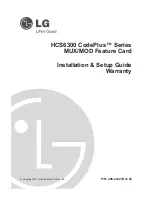
SCHEMATIC CIRCUITRY
& CONNECTION DIAGRAM
:
Low Drift
Amplifier&Burnout
Output
Isolation
1
2
4
7
8
3
6
10
+
+
OUT
S1
POWER
A
11
Driver
Digital
Computation
Circuit
5
9
S2
S1
S2
S.D
B
b