RTA 460BSSC-NNA1, Product User Manual
The RTA 460BSSC-NNA1 is a high-quality product equipped with advanced features. It comes with a comprehensive Product User Manual, which you can download for free from manualshive.com. This manual provides detailed instructions, making it easy for users to understand and optimize the full potential of this remarkable product.
Share
Download


Reviews:
No comments
Related manuals for 460BSSC-NNA1

LoRaWAN
Brand: IDEETRON Pages: 12

MG1
Brand: Pace Pages: 2

FBI6119-0400
Brand: TCS Pages: 56

GW1108 Series
Brand: 3onedata Pages: 5

ICG-2420-LTE
Brand: Planet Pages: 12

SmartNode 5540E Series
Brand: Patton Pages: 77

GXW4500 Series
Brand: Grandstream Networks Pages: 20

MultiVOIP MVPFX2-8
Brand: Multitech Pages: 8

MP-272-DB
Brand: AudioCodes Pages: 2

VRF
Brand: Gree Pages: 31

SR360n
Brand: SmartRG Pages: 122

6000-B1
Brand: Innoband Pages: 87

GT704WGB
Brand: ActionTec Pages: 73

Envoy-S Standard ENV-S-WB-230-F
Brand: enphase Pages: 2

TG797n V3
Brand: Telstra Pages: 34

WiPG-1500
Brand: WePresent Pages: 68

5G21-12W-A
Brand: T-Mobile Pages: 48
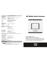
Mobile Audio Gateway
Brand: 2N Pages: 2


