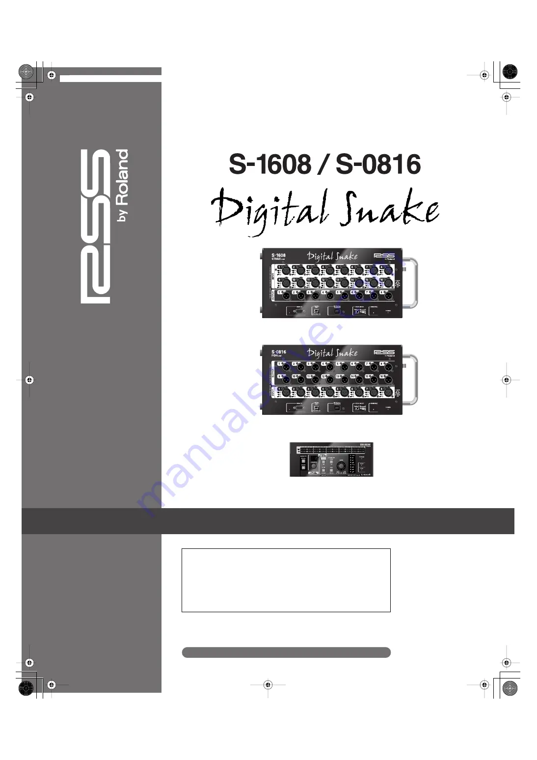
background image


Owner’s Manual

S-1608 STAGE UNIT

S-0816 FOH UNIT

S-4000R REMOTE CONTROLLER


Before using this unit, carefully read the sections entitled: “IMPORTANT
SAFETY INSTRUCTIONS” (Owner’s Manual Pg. 2), “USING THE UNIT SAFELY”
(Owner’s Manual Pg. 3–4), and “IMPORTANT NOTES” (Owner’s Manual Pg.
5). These sections provide important information concerning the proper
operation of the unit. Additionally, in order to feel assured that you have
gained a good grasp of every feature provided by your new unit, Owner’s
Manual should be read in its entirety. The manual should be saved and kept
on hand as a convenient reference.


Copyright


©


2007 ROLAND CORPORATION


All rights reserved. No part of this publication may be reproduced in any 
form without the written permission of ROLAND CORPORATION.


http://www.rolandsystemsgroup.net

S-1608_e.book 1 ページ 2007年11月8日 木曜日 午後12時1分

Summary of Contents for Digital Snake S-1608

Page 1: ... concerning the proper operation of the unit Additionally in order to feel assured that you have gained a good grasp of every feature provided by your new unit Owner s Manual should be read in its entirety The manual should be saved and kept on hand as a convenient reference Copyright 2007 ROLAND CORPORATION All rights reserved No part of this publication may be reproduced in any form without the ...

Page 2: ... and a third grounding prong The wide blade or the third prong are provided for your safety If the provided plug does not fit into your outlet consult an electrician for replacement of the obsolete outlet WARNING IMPORTANT As the colours of the wires in the mains lead of this apparatus may not correspond with the coloured markings identifying the terminals in your plug proceed as follows The wire ...

Page 3: ...ord Also the supplied power cord must not be used with any other device 009 Do not excessively twist or bend the power cord nor place heavy objects on it Doing so can damage the cord producing severed elements and short circuits Damaged cords are fire and shock hazards 011 Do not allow any objects e g flammable material coins pins or liquids of any kind water soft drinks etc to penetrate the unit ...

Page 4: ...s alcohol nail polish spray cans etc near the unit Swiftly wipe away any liquid that spills on the unit using a dry soft cloth 101a The unit should be located so that its location or position does not interfere with its proper ventilation 102b Always grasp only the plug on the power supply cord when plugging into or unplugging from an outlet or this unit 103a At regular intervals you should unplug...

Page 5: ...t to stand for several hours until the condensation has completely evaporated 360 Depending on the material and temperature of the surface on which you place the unit its rubber feet may discolor or mar the surface You can place a piece of felt or cloth under the rubber feet to prevent this from happening If you do so please make sure that the unit will not slip or move accidentally Maintenance 40...

Page 6: ... Front Panel 17 S 0816 Front Panel 17 S 1608 S 0816 Side Panel 20 S 4000R Remote Controller 22 S 4000R Front Panel 22 S 4000R Rear Panel 24 5 S 1608 S 0816 System Overview 25 Concept 25 Things to Know 26 About REAC 26 Understanding Cables and Connections 26 Cat5e Ethernet Cable Types 26 Ethernet Connectors 27 About Ethernet Switching Hubs 28 A D D A Conversion and Signal Optimization 29 RS 232C Se...

Page 7: ... Cable Requirements 40 REAC Cable Length Extension 41 REAC Connection Notes 41 Notes About Handling Cat5e Cables REAC Cables 42 Connecting the S 4000R Remote Controller 42 Audio Connections 43 S 1608 S 0816 Audio Connections 43 S 1608 S 0816 Audio Inputs 44 Input Status Indicators 45 S 1608 S 0816 Audio Outputs 45 Powering Up 46 Powering Up 46 Powering Off 46 System Status Indicators 47 Power Indi...

Page 8: ...a Single S 1608 S 0816 System 55 Computer Control S 4000 RCS 56 Where to Get the S 4000 RCS 56 System Requirements 56 Splitting Stage Audio to Multiple Destinations 56 What You ll Need 57 Ethernet Switching Hub Requirements 57 Split Connection Overview 58 Notes on Split Setups 59 Setting the REAC MODE Switches 59 REAC Connections 60 Audio Connections and Power Up 61 8 Applications 62 16x8 System 6...

Page 9: ...nnectors 69 Cat5e Crossover Wiring REAC cable SC W100S 69 Cat5e Straight Through Wiring 69 RS 232C REMOTE Connector D Sub DB 9 type 70 S 1608 S 0816 Audio Connectors XLR type 70 Appendix C Ethernet Switching Hub Requirements 71 Appendix D Specifications 72 Specifications S 1608 STAGE UNIT 72 Specifications S 0816 FOH UNIT 73 Specifications S 4000R REMOTE CONTROLLER 74 Appendix E Dimensions 75 Dime...

Page 10: ...Snake we recommend reading the entire manual The material is presented in the following chapters Main Features briefly describes the features and benefits of the system and its components Components and Accessories lists what s included with the S 1608 S 0816 System and some of the available system options Panel Descriptions show you where everything is and what it s for S 1608 S 0816 System Overv...

Page 11: ... usually over a long distance Since the S 1608 S 0816 System transfers signals as digital data the system s primary benefit it s called a digital snake In most cases audio snakes are used in sound reinforcement applications that involve a musical performance a theatre presentation or an orator or orators In such applications the primary source of the audio is at a stage area and that audio is sent...

Page 12: ...e Documents In addition to the S 1608 S 0816 Digital Snake Owner s Manual carefully read the following manuals included with the S 4000 System S 4000R Installation Manual These manuals provide important information concerning the proper operation of each unit and detail precautions for using the units safely A warning contains important information that will help you avoid damage to the S 1608 S 0...

Page 13: ...C or Mac S 1608 Stage Unit Stage unit with 16 inputs and 8 outputs on XLR connectors All new precision designed preamps with massive headroom and clean warm sound gain range from 65 to 10 dBu typical 28 dBu maximum input level Audio signal and system status indicators REAC port for connecting with S 0816 or other REAC device RS 232C interface for S 4000R Remote Controller or computer control MUTE ...

Page 14: ...r and pad for each S 1608 S 0816 input channel Clean input gain adjustment 1 dB steps Ten memory presets for storing frequently used input setups Eight segment LED meter for precise input signal level monitoring Signal status indicators for all 24 channels System status indicators System lock for protection of channel settings S 1608_e book 14 ページ 2007年11月8日 木曜日 午後12時1分 ...

Page 15: ...16 1 AC power supply cord 2 5 meters 1 REAC connector cover 1 Rack mounting hardware kit 1 left side rack mount bracket 1 Right side rack mount bracket 1 AC cord clamp Attached to the side panel of the S 1608 1 Ferrite core 4 Rubber Foot 1 S 1608 S 0816 Digital Snake Owner s Manual Accessories for S 4000R 1 RS 232C cable 3 meters 1 Rack mounting hardware kit 2 Rack mount brackets 4 Screws 1 S 4000...

Page 16: ...options S 4000 Remote Control Software S 4000 RCS Computer control software for PC Mac free download from www rolandsystemsgroup net SC W100S Heavy duty 100 meter Cat5e Ethernet crossover cable with Neutrik EtherCon connectors S 4000 SP REAC Splitter System Options S 1608_e book 16 ページ 2007年11月8日 木曜日 午後12時1分 ...

Page 17: ...608 S 0816 Digital Snake Owner s Manual 17 4 Panel Descriptions S 1608 Front Panel fig 4 01 eps S 0816 Front Panel fig 4 01 eps S 1608 Stage Unit S 0816 FOH Unit S 1608_e book 17 ページ 2007年11月8日 木曜日 午後12時1分 ...

Page 18: ...remote control and signal monitoring of the S 1608 S 0816 System from an external device supporting the RS 232C serial interface protocol Normally you d connect the S 4000R Remote Controller to this connector using the supplied DB 9 cable If you re using the S 4000 RCS on a computer connect the computer s RS 232C port to this connector Although changes may not seem smooth when adjusting preamp gai...

Page 19: ...608 S 0816 as a Slave REAC device SP configures the S 1608 S 0816 as a Split REAC device 8 REAC Indicator This indicator lights when REAC communication is established within the S 1608 S 0816 System If REAC communication fails this indicator will flash and then go out 9 Power Indicator This indicator lights when the S 1608 S 0816 is receiving power from its internal power supply The system outputs...

Page 20: ...lly pulled out 2 Grounding Terminal If necessary use this terminal to connect the S 1608 S 0816 chassis to an external grounding source 3 AC Cord Clamp This clamp holds the AC power cord in place See Page 34 for more information Use only the supplied power cord to prevent damage to the S 1608 S 0816 Never attempt to use the following sources for an external ground connection Water pipes may result...

Page 21: ...litter S 4000 SP or Ethernet switching hub This port uses Neutrik EtherCon RJ45 connectors for a robust connection Standard RJ45 plugs can be connected here as well 7 Security Slot http www kensington com Be sure never to block the cooling fan exhaust vents and air intake vents Doing so may cause the S 1608 S 0816 to overheat and be damaged See Chapter 5 for information about the types of Ethernet...

Page 22: ...L and STORE buttons to recall and store settings 3 CHANNEL Knob and CHANNEL Display Use the CHANNEL knob to select an input channel for editing or signal level monitoring The currently selected channel is shown in the CHANNEL display The CHANNEL knob and CHANNEL display are also used to select memory presets and link odd even channel pairs Stereo Link function S 4000R Remote Controller The S 4000R...

Page 23: ... dBu with the pad on and 65 to 10 dBu with the pad off 7 Input Signal Level Meter This eight segment LED meter indicates signal level for the currently selected input channel 8 LOCK Button The LOCK button allows you to lock the S 4000R so that input channel settings cannot be altered The S 4000R is locked when the LOCK button is lit To unlock the S 4000R hold the LOCK button until its light goes o...

Page 24: ... S 0816 System If REAC communication fails this indicator will flash 12 CTRL Indicator The indicator lights when the S 4000R is connected to a powered on S 1608 or S 0816 and communication is established S 4000R Rear Panel fig 4 06 eps 1 REMOTE Connector Use the supplied RS 232C cable to connect the S 4000R s REMOTE connector to the REMOTE connector on either the S 1608 or S 0816 Always turn the p...

Page 25: ...very expensive On top of that analog signals traveling through hundreds of feet of cable always have some degree of high frequency loss and overall degradation due to cable capacitance inductance and resistance Meets the New Generation The fundamental benefit of the digital snake is that it eliminates long analog audio signal transfers and the signal degradation and noise interference that always ...

Page 26: ...de using Cat5e short for Enhanced Category 5 Ethernet cable This cable is a standard in the computer connection world in fact you may be using an Ethernet cable in your home or office right now to connect your computer to a high speed modem a printer or a network This lightweight cable uses RJ45 plugs which are very similar to standard telephone connectors Cat5e Ethernet Cable Types There are two ...

Page 27: ... EtherCon connectors this provides a robust latching connection similar to that provided by an XLR connector Neutrik offers EtherCon connectors for the fabrication of new cables models NE8MC 1 and NE8MC 1 B and EtherCon connectors that can be added to a pre made Ethernet cable models NE8MC and NE8MC B Ethernet connection standards recommend using straight through cables to connect devices to the p...

Page 28: ...tem Use a switching hub when you need to extend the REAC cable length The maximum length for a single REAC cable is 100 meters However if you need to extend the cable length you can use two cables REAC cables or Cat5e cables with a switching hub in line to refresh the REAC signal and extend it another 100 meters Up to four switching hubs can be used for a maximum cable length extension of 500 mete...

Page 29: ...variable gain preamps on each of its 24 audio inputs This allows for signal optimization at the source resulting in the highest A D conversion quality RS 232C Serial Interface The S 1608 and S 0816 feature REMOTE connectors that support the RS 232C serial interface protocol RS 232C is a standard communications interface found in computers The S 1608 S 0816 System can be controlled from a remote de...

Page 30: ...t the S 1608 S 0816 System s inputs Better analog signal quality By adjusting the input gain so close to the source the analog signal travels through less analog cabling before the signal level is optimized Shorter analog cabling means less possibility of noise and signal deterioration Better digital signal quality A D converters take snapshots of the analog audio during the digital conversion pro...

Page 31: ...stem s 24 input channels Memory presets 10 memory presets allow you to store and recall frequently used S 1608 S 0816 System s input channel setups Computer Control All functions that can be controlled from the S 4000R can also be controlled from a personal computer equipped with an RS 232C port s and running the S 4000 Remote Control Software S 4000 RCS Up to four S 1608 S 0816 Systems can be con...

Page 32: ...w and ventilation Do not allow the vents to become obstructed Avoid using the S 1608 or S 0816 in sealed type rack mounts As this type of rack does not permit heated air within the rack to be expelled the heated air is drawn into the S 1608 or S 0816 as a result thus preventing adequately efficient cooling If the rack s rear panel is not removable ensure that a ventilation port or exhaust fan is p...

Page 33: ...er is designed for handheld or desktop use If desired it can be rack mounted by installing the included rack mount brackets Use the following procedure to install the rack mount brackets on the S 4000R 1 Disconnect the RS 232C cable from the S 4000R unit 2 Install the S 4000R rack mount brackets with the supplied screws as shown in the following diagram fig 6 08 eps S 1608_e book 33 ページ 2007年11月8日...

Page 34: ...ed out accidentally 1 Remove only the screws shown in the following diagram 2 screws total and detach the AC cord clamp fig 6 01 eps 2 As shown in the figure clamp the AC power cord with the AC Cord Clamp and secure with the screws 2 removed in Step 1 You can also prevent the AC power cord from being unplugged by wrapping it around the handle S 1608_e book 34 ページ 2007年11月8日 木曜日 午後12時1分 ...

Page 35: ...45 plug that will be connected to a REAC port Use the following procedure to install a ferrite core on an Ethernet cable 1 Lift up the ferrite core s tabs and open the ferrite core fig 6 11 eps 2 Place the REAC cable SC W100S or Ethernet cable in the ferrite core so that the core abuts the base of the cable s connector fig 6 12 eps 3 Push the tabs until they close securely with a snapping sound fi...

Page 36: ... Ethernet cable with standard RJ45 plugs fit the included REAC connector cover on the REAC port as shown fig 6 09 eps_50 Attaching the Rubber Feet Attach these as required such as when you re using the S 1608 or S 0816 without mounting it on a rack or the like Peel off the double sided tape from the rubber feet and affix the rubber feet at the locations shown in the following figure Remove the REA...

Page 37: ...own the volume and turn off the power on all devices before making any connections S 1608 16x8 Master REAC device S 0816 8x16 Slave REAC device 8 outputs from console REAC cable SC W100S or Cat5e cable 16 mic line inputs S 4000R Remote Controller RS 232C cable 8 outputs from console 16 mic line sources from stage REMOTE connector on S 1608 or S 0816 S 1608_e book 37 ページ 2007年11月8日 木曜日 午後12時1分 ...

Page 38: ... be many Split REAC devices in a system In most circumstances it s best to make the main stage connection unit the Master REAC device and the FOH unit the Slave REAC device This configuration allows you to split the stage audio to multiple destinations see Chapter 7 You can expand your system by using an additional S 0816 at a split location This will deliver the 16 inputs from the Stage Master un...

Page 39: ...ly To change the switch setting use a blunt tipped instrument such as a ball point pen mechanical pencil etc With their power off set the units as follows 1 On the S 1608 set the REAC MODE switch to M 2 On the S 0816 set the REAC MODE switch to S If the REAC MODE switch setting is changed when the unit is powered on the new setting won t take effect until the unit is powered off and then back on a...

Page 40: ...internal power supply REAC Connections Cable Requirements A single cable REAC to REAC connection requires a standard Cat5e Ethernet cable with RJ45 plugs wired in a straight through or crossover configuration The maximum length for a single cable is 100 meters 330 feet fig 6 17 eps Component Connections Use only the supplied power cords to prevent damage to the units As a reminder a REAC to REAC c...

Page 41: ...tputs To avoid this turn down the volume and or power off any devices connected to the S 1608 S 0816 Or connect disconnect the REAC cable while MUTE ALL OUTPUTS is held If the REAC cable is disconnected while MUTE ALL OUTPUTS is held it s possible that one of the S 1608 or S 0816 will remain in a muted state when MUTE ALL OUTPUTS is released If this occurs use the following procedure 1 Reconnect t...

Page 42: ... through the REMOTE connection The S 4000R s POWER indicator will light when receiving power If you require a longer cable than the one provided you can use an off the shelf RS 232C cable or fabricate your own See Appendix B Connector Information for an RS 232C pin out diagram The S 4000R can be connected to either the S 1608 or S 0816 Connect it to whichever device location is most convenient for...

Page 43: ...utputs and prevent possible damage to connected speakers and other devices See Page 48 for more information about MUTE ALL OUTPUTS Note that MUTE ALL OUTPUTS only mutes the outputs of the S 1608 S 0816 System and not the outputs of other devices Before connecting the audio outputs on the S 1608 and S 0816 units to the audio inputs of other devices always turn down the volume or turn off the power ...

Page 44: ...ng fig 6 27 eps To connect high impedance sources such as the output of an electric guitar or bass with passive pickups use a direct box or impedance matching transformer in line When connecting unbalanced sources that require long cable runs over 6 meters a direct box or balancing adaptor placed in line near the source is recommended for the best audio quality and noise rejection Howling feedback...

Page 45: ...16 s balanced audio outputs to the balanced audio inputs of the desired devices If you need to connect the S 1608 s S 0816 s audio outputs to unbalanced devices use a direct box or balancing adaptor in line or a cable adaptor with the wiring described in the previous section S 1608 S 0816 Audio Inputs The CLIP and SIG signal status indicators represent the signal level in the digital domain post A...

Page 46: ... power off the S 1608 S 0816 System 1 Turn down the volume and power off any devices connected to the S 1608 and S 0816 units inputs and outputs Note It s always best to turn down the volume and power off any speakers or amplification systems first 2 If an S 4000R is connected to the system press and hold the S 4000R s LOCK button until its indicator lights Locking the S 4000R retains the current ...

Page 47: ...ndicators Remote Communication The S 1608 and S 0816 have REMOTE indicators and the S 4000R has CTRL indicator that show when RS 232C communication is established within the system On the S 1608 and S 0816 units fig 6 34 eps REMOTE lights when an RS 232C device such as the S 4000R is connected to the S 1608 S 0816 System and communication is established If no RS 232C device is connected to the S 1...

Page 48: ...ystem outputs will become un muted after releasing MUTE ALL OUTPUTS If audio is passing through the system when MUTE ALL OUTPUTS is released the sound may be distorted until the system outputs are completely un muted Note that MUTE ALL OUTPUTS only mutes the outputs of the S 4000 System and not the outputs of other devices Before connecting the audio outputs on the S 1608 and S 0816 units to the a...

Page 49: ...current channel settings from accidental changes during a live performance To lock the S 4000R press LOCK so its indicator lights When locked S 1608 and S 0816 channel settings cannot be adjusted To unlock the S 4000R press and hold LOCK until its indicator goes out approximately 1 5 seconds When unlocked S 1608 and S 0816 channel settings can be adjusted Using the S 4000R Remote Controller When t...

Page 50: ...CLIP CLEAR ENTER so its indicator goes out To keep a channel s CLIP indicator from lighting again lower the preamp gain on that particular channel see Page 51 for more information LED Input Meter The S 4000R features an eight segment LED input meter for precise input signal measurement To view an input channel s signal level with the LED input meter turn the CHANNEL knob to select the desired chan...

Page 51: ... use the GAIN knob to adjust the preamp gain to the desired level fig 6 41 eps If the signal level exceeds 0 dB the CLIP indicators on the LED input meter and signal status indicators will light and distortion will occur For the best audio quality set the preamp gain so the meter reads between 18 and 3 dB on the input signal s loudest peaks 4 Repeat Steps 1 3 to adjust other channels preamp gain T...

Page 52: ...ndenser microphones or active direct boxes fig 6 43 eps Use the following procedure to turn on phantom power on a particular channel 1 Select the desired channel 1 24 with the CHANNEL knob 2 Press PHANTOM 48 V so its indicator lights 3 Repeat Steps 1 2 to turn on other channels phantom power To turn off a channel s phantom power select the channel with the CHANNEL knob and then press PHANTOM 48 V ...

Page 53: ...e 3 Release CLIP CLEAR ENTER When channels are linked their channel numbers are displayed with two periods as shown in the following examples fig 6 44 eps With the S 4000R unlocked use the following procedure to unlink a channel pair 1 Using the CHANNEL knob select one channel of the linked pair that you wish to unlink 2 While holding CLIP CLEAR ENTER turn the CHANNEL knob counterclockwise 3 Relea...

Page 54: ...ngs to another memory preset repeat Steps 2 3 To exit Memory Store mode press STORE so that its indicator goes out Recalling a Memory Preset Memory Recall Mode To recall a memory preset 1 Press and hold RECALL until its indicator lights solid 2 Turn the CHANNEL knob until the desired memory preset 0 9 is shown in the CHANNEL display The currently loaded preset displays a period next to the preset ...

Page 55: ...ther unit fig 7 01 eps The following behaviors occur when two S 4000Rs are used in a single system Only one S 4000R unit can be used to edit S 1608 S 0816 system s channels and recall store memory presets at any one time When one S 4000R unit is in use the other S 4000R unit automatically enters a locked state and its LOCK button flashes Using Two S 4000R Units in a Single S 1608 S 0816 System See...

Page 56: ...wnload from www rolandsystemsgroup net Refer to the documentation included with software for instructions on using it with the S 1608 S 0816 System System Requirements The S 4000 RCS is available for both Windows and Macintosh operating systems Please visit www rolandsystemsgroup net for the latest S 4000 RCS version and current computer and operating system requirements As we ve discussed previou...

Page 57: ... loss in quality What You ll Need To split the S 1608 s 16 channels of input audio you ll need a REAC splitter S 4000 SP or an Ethernet switching hub with enough ports to connect each REAC device an additional S 0816 unit for each split destination REAC cable SC W100S or Cat5e cables Ethernet Switching Hub Requirements To work with REAC an Ethernet switching hub must meet the following requirement...

Page 58: ... Split REAC device S 1608 16x8 Master REAC device when connected to a Split device levels and parameters can be monitored but not adjusted Monitor Console 16 mic line sources from the stage 8 outputs from console 16 mic line inputs REAC cable SC W100S or Cat5e cable S 0816 8x16 Slave REAC device 16 mic line sources from stage 8 outputs from console REAC cable SC W100S or Cat5e cable S 1608_e book ...

Page 59: ...d to adjust the signal level coming from a Split device s outputs use the input trim controls on the receiving device Setting the REAC MODE Switches With their power off set the units as follows 1 On the S 1608 set the REAC MODE switch to M 2 On the primary S 0816 usually at the FOH position set the REAC MODE switch to S 3 On each S 0816 used to receive audio splits from the stage set the REAC MOD...

Page 60: ...meters a separate REAC splitter or switching hub must be used in line See REAC Cable Length Extension in Chapter 6 for more information As mentioned earlier in the manual some switching hubs have ports that allow the use of either crossover or straight through cables they will detect the type of cable that s connected and adjust the signal transfer accordingly Consult the documentation for the swi...

Page 61: ...he Master and Slave REAC devices audio inputs 5 Turn on the power on the REAC splitter s or the switching hub s 6 Power up the Master Slave and Split devices so that their POWER indicators light 7 Turn on the power to the audio devices mixing consoles power amplifiers monitor speakers etc connected to the Master Slave and Split devices audio outputs In each of the following steps allow each piece ...

Page 62: ...fig 8 01 eps_80 16x8 System S 1608 16x8 Master REAC device S 0816 8x16 Slave REAC device REAC cable SC W100S or Cat5e cable 8 outputs from console 16 mic line inputs 8 outputs from console 16 mic line sources from stage S 1608_e book 62 ページ 2007年11月8日 木曜日 午後12時1分 ...

Page 63: ...Ethernet switching hub S 1608 16x8 Master REAC device 8 outputs from console 16 mic line inputs S 0816 8x16 Split REAC device REAC cable SC W100S or Cat5e cable S 0816 8x16 Slave REAC device 16 mic line sources from stage 16 mic line sources from the stage Monitor Console 8 outputs from console S 1608_e book 63 ページ 2007年11月8日 木曜日 午後12時1分 ...

Page 64: ...8 03 eps_90 32x16 System REAC cable SC W100S or Cat5e cable 2 S 1608 16x8 Master REAC device 2 S 0816 8x16 Slave REAC device 16 outputs from console 32 mic line sources from stage 32 mic line inputs 16 outputs from console S 1608_e book 64 ページ 2007年11月8日 木曜日 午後12時1分 ...

Page 65: ...ts from console 32 mic line inputs S 4000 SP or Ethernet switching hub 2 S 0816 8x16 Slave REAC device 2 S 0816 8x16 Split REAC device REAC cable SC W100S or Cat5e cable REAC cable SC W100S or Cat5e cable 16 outputs from console 32 mic line sources from stage 32 mic line sources from the stage Monitor Console S 1608_e book 65 ページ 2007年11月8日 木曜日 午後12時1分 ...

Page 66: ...or the latest information about the S 1608 S 0816 System SI SI Empty Empty Empty Empty Empty Empty Empty Empty Empty Empty SI SI SI SI SO SO SO SO SO SO SI AD4 SI AES4 SO DA4 SO AES4 SI SO S 0816 8x16 S 1608 16x8 S 4000S S 4000S S 4000H S 1608 16x8 REAC cable SC W100S or Cat5e cable REAC cable SC W100S or Cat5e cable REAC cable SC W100S or Cat5e cable Be sure to set the REAC mode of the S 4000H to...

Page 67: ...ge 40 If a switching hub is used is it working If a switching hub is used is it properly connected See Page 41 60 If a switching hub is used does it have the proper specification See Appendix C Dark System power up None normal operation REMOTE Lit REMOTE communication established None normal operation Dark No device is connected to REMOTE jack None normal operation Flashing Dark No REMOTE communic...

Page 68: ...wiring See Appendix B S 4000R Unit Error Indicators Indicator Status Definition Troubleshooting Action CLIP 1 SIG 1 Lit The REAC connection has failed Check REAC cabling Check REAC connections Check in line REAC Splitter S 4000 SP or switching hub if used on REAC connection Flashing Recovery from the above error None CLIP 2 Lit An exhaust fan on the Master REAC unit has stopped working Check the e...

Page 69: ...t used in this application but may be wired in the cable as shown Cat5e Straight Through Wiring fig app 02 eps Note Pins 4 5 7 and 8 are not used in this application but may be wired in the cable as shown Appendix B Connector Information 1 2 3 4 5 6 7 8 1 2 3 4 5 6 7 8 TX TX RX RX TX TX RX RX 1 2 3 4 5 6 7 8 1 2 3 4 5 6 7 8 TX TX RX RX TX TX RX RX S 1608_e book 69 ページ 2007年11月8日 木曜日 午後12時1分 ...

Page 70: ...Audio Connectors XLR type S 1608 S 0816 XLR Audio Pin Outs INPUT and OUTPUT Balanced connections recommended fig app 05 eps Unbalanced connections fig app 06 eps Pin Number Signal Name Pin Connection 1 NC 2 TxD Data Out 3 RxD Data In 4 NC 5 GND 6 5 V 7 Short to Pin 8 8 Short to Pin 7 9 NC 8 6 9 7 5 4 9 8 7 6 3 5 3 1 1 2 4 2 9 8 7 6 5 3 1 4 2 Included RS 232C cable GROUND HOT COLD 1 3 2 GROUND HOT ...

Page 71: ...e this amount of data traffic Gigabit Ethernet switching hubs can handle a larger amount of data traffic so we recommend them for use with REAC devices just be sure that the Gigabit switching hub you use supports 100BASE TX devices When using switching hubs in line for REAC cable length extension a maximum of four hubs can be used Total cable length with four switching hubs 500 meters See Chapter ...

Page 72: ...PAD On 1 dB step Max 28 dBu PAD 20 dB On Off Input Impedance 14 k ohms Nominal Output Level 4 dBu Max 22 dBu Output Impedance 600 ohms Recommended Load Impedance 10 k ohms or greater Residual Noise Level IHF A typ 80 dBu or less Equivalent Input Noise Level E I N 128 dB Network Latency 375 microseconds when using REAC cable only 1 AD REAC DA Latency about 1 2 ms Connectors Input x 16 XLR type bala...

Page 73: ...ep Max 28 dBu PAD 20 dB On Off Input Impedance 14 k ohms Nominal Output Level 4 dBu Max 22 dBu Output Impedance 600 ohms Recommended Load Impedance 10 k ohms or greater Residual Noise Level IHF A typ 80 dBu or less Equivalent Input Noise Level E I N 124 dB Network Latency 375 microseconds when using REAC cable only 1 AD REAC DA Latency about 1 2 ms Connectors Input x 16 XLR type balanced phantom p...

Page 74: ...cators 1 40 POWER Indicator REAC Indicator CTRL Indicator Level Meter CHANNEL Display 8 segments 2 digits GAIN Indicators 15 steps Memory 10 memory presets Power Supply Supplied from connected device S 1608 or S 0816 through the remote cable Dimensions 215 W x 87 D x 54 6 H mm 8 1 2 W x 3 7 16 D x 2 3 16 H inches Weight 0 8 kg 1 lb 13 oz Operation Temperature 0 to 40 degrees Celsius 32 to 104 degr...

Page 75: ...608 S 0816 Digital Snake Owner s Manual 75 Dimensions S 1608 Note Dimensions are shown in millimeters fig app 12 eps Appendix E Dimensions 101 6 177 135 482 465 401 177 135 S 1608_e book 75 ページ 2007年11月8日 木曜日 午後12時1分 ...

Page 76: ...dices 76 S 1608 S 0816 Digital Snake Owner s Manual Dimensions S 0816 Note Dimensions are shown in millimeters fig app 13 eps 135 101 6 177 135 482 465 177 135 401 S 1608_e book 76 ページ 2007年11月8日 木曜日 午後12時1分 ...

Page 77: ...pendices S 1608 S 0816 Digital Snake Owner s Manual 77 Dimensions S 4000R Note Dimensions are shown in millimeters fig app 14 eps 215 87 8 54 3 60 9 8 9 2 54 6 S 1608_e book 77 ページ 2007年11月8日 木曜日 午後12時1分 ...

Page 78: ...icator 18 45 pin out diagrams 69 70 power connections S 1608 S 0816 40 S 4000R 42 powering off 46 powering up S 1608 S 0816 System 46 S 1608 S 0816 System with splits 61 Preamp 30 R rack mounting S 1608 S 0816 32 S 4000R 33 REAC about 26 cables 26 40 41 checking Indicators 47 67 68 connecting cables 40 42 connecting cables for splits 60 connection cover 36 connectors RJ45 27 redundant connections ...

Page 79: ...ence to radio communications However there is no guarantee that interference will not occur in a particular installation If this equipment does cause harmful interference to radio or television reception which can be determined by turning the equipment off and on the user is encouraged to try to correct the interference by one or more of the following measures Reorient or relocate the receiving an...

Page 80: ...35500 Gheorgheni ROMANIA TEL 266 364 609 AUSTRIA BELGIUM FRANCE GERMANY HOLLAND LUXEMBOURG PORTUGAL SPAIN SWITZERLAND Roland Iberia S L Paseo García Faria 33 35 08005 Barcelona SPAIN TEL 93 493 91 00 CROATIA ART CENTAR Degenova 3 HR 10000 Zagreb TEL 1 466 8493 CZECH REP CZECH REPUBLIC DISTRIBUTOR s r o Voctárova 247 16 CZ 180 00 PRAHA 8 CZECH REP TEL 2 830 20270 DENMARK Roland Scandinavia A S Nord...

Reviews: