background image

1

5.25" Floppy Disk Drive

Stock No. 237-088

1.0

Introduction

1.1

General description

This drive is a high-density, dual speed, double-sided 5.25" mini-floppy disk drive.
The speed is controlled by Pin #2 of the interface connector.  Normally, when this pin
is at logical low, the transfer rate is low and when at logical high, the transfer rate is
high.  This drive can be used as a high-density 1.6Mb drive.  When at logical low,
this drive can be used as a standard 1.0Mb drive.

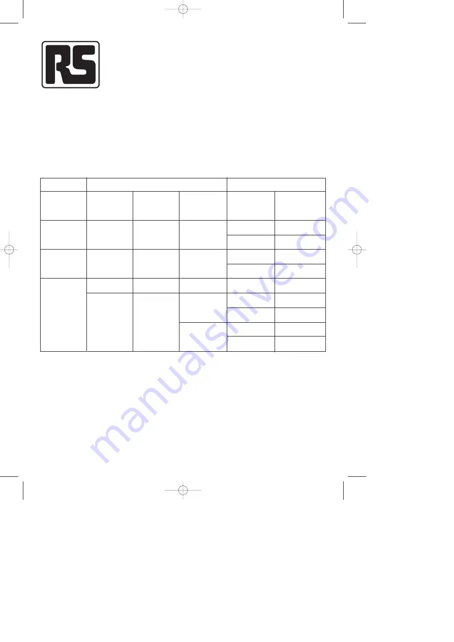
Table 1-1.  Compatibility with other model drives

Read by this drive

Double-sided

48 t.p.i.

Double-sided

96 t.p.i.

Dual-speed

0.5Mb

1.0Mb

1.6Mb

1.0Mb

300 r.p.m.

300 r.p.m.

300 r.p.m.

360 r.p.m.

MD

MD

HD

MD

FDD used

Diskette

Capacity

360 r.p.m.

300 r.p.m.

360 r.p.m.

300 r.p.m.

360 r.p.m.

360 r.p.m.

360 r.p.m.

300 r.p.m.

360 r.p.m.

360 r.p.m.

Rotational

speed

Rotational

speed

Transfer rate

300Kbits/sec

250Kbits/sec

300Kbits/sec

250Kbits/sec

500Kbits/sec

300Kbits/sec

250Kbits/sec

300Kbits/sec

250Kbits/sec

Diskette written

 Leaflet No. 9419  26/4/97 6:09 pm  Page 1

Summary of Contents for 237-088

Page 1: ...gical low this drive can be used as a standard 1 0Mb drive Table 1 1 Compatibility with other model drives Read by this drive Double sided 48 t p i Double sided 96 t p i Dual speed 0 5Mb 1 0Mb 1 6Mb 1...

Page 2: ...000 833 333 802 083 Per surface 250 000 416 666 401 041 Per track 3 125 5 208 IBM format MFM 16 sectors track 15 sectors track Per drive 655 360 1 228 800 1 182 720 Per surface 327 680 614 400 591 360...

Page 3: ...1 per 109 bits read Hard error rate 1 per 1012 bits read Seek error 1 per 106 seeks Media life Number of passes per track 3 5 x 10⁶ Number of media clamp 3 0 x 104 1 2 4 Physical specifications Shippi...

Page 4: ...rements represent the values in the case where a media with a media load of 100g cm is used 4 Item Rating Power requirement Power consumption 12V 5V Current Current During operation During operation 1...

Page 5: ...internal functions are shown in figure 1 2 1 3 1 Read write control electronics The electronics package contains a Index detector circuits b Head positioning driver circuits c Read write amplifier an...

Page 6: ...ks Thus normal interchange tolerances between media and drives will not degrade the signal to noise ratio and diskette interchangeability is ensured The heads are mounted on a carriage which is locate...

Page 7: ...ve select 4 lines Track 0 Index Motor on Side select Ready drive status Mode select Write data Write gate Write protect Read data Write logic Read logic Control logic Index In use LED Index detector S...

Page 8: ...rive select 3 Drive select 4 Motor ON Direction select Step Write data Write gate Side select In use spare option Mode select 12V 12V Return 5V Return 5V 1 2 3 4 100kW 0 01mF Signal ground Frame groun...

Page 9: ...e drives on a daisy chain remove all plug jumpers TM except for the last drive on the daisy chain The input signal lines which are not multiplexed are MOTOR ON and IN USE The input lines have the foll...

Page 10: ...the drive 2 2 3 Motor on J1 pin 16 The motor on signal causes the drive s spindle drive motor to turn on In standard configuration jumpers MS open this input signal line when true logic low will activ...

Page 11: ...ck ID address field In the event that the controller loses track of the head carriage assembly s location it is recommended that direction select be set to a logic high level and several step pulses b...

Page 12: ...Please see the OP AT AX BX 1M plug option section 2 3 Output lines The drive has five active signal lines for its output Each output line is driven by a 7438 or equivalent open collector output gate...

Page 13: ...ignal informs the host system about the status of the drive By choosing appropriate plug options RDY DC DD TH plugs the following conditions of pin 34 could be achieved Please see section 3 2 7 1 Read...

Page 14: ...fications and their P2 J2 pin designation is outlined in table 2 1 Table 2 1 D C power requirements 12V and 5V ground returns are tied together at drive PCB 14 Not Insert Insert Power On Media Drive s...

Page 15: ...ground distribution To provide optimum performance and noise immunity extreme care must be used to provide low noise grounds Independent frame ground wires should run from each drive and other system...

Page 16: ...d be provided by the 17 signal ground pins of the J1 connector All odd pins 1 through 33 should be connected to the controller signal ground plane Note 1 Shield power cable should be only one and tied...

Page 17: ...tion is not required 2 7 2 Read operation Reading data from the drive is accomplished by a Activating the DRIVE SELECT line b Selecting the head c WRITE GATE being inactive The timing requirements for...

Page 18: ...s of modifications and how to implement them 3 1 Plug wire jumper The drive can be modified by the user according to the user s requirements These modifications can be implemented by adding changing o...

Page 19: ...drive select and in use Enables drive motor with drive select Dual mode Dual mode positive high density Dual speed Mode select with latched by DS Single mode 1Mb only Termination resistor Standard re...

Page 20: ...Closed Closed Closed Closed Closed Closed Closed Closed Closed Closed Closed Closed Closed Closed Closed Closed Closed Closed Closed Closed Closed Closed Open Open Open Open Open Open Open Open Open O...

Page 21: ...is installed Note 7 Open Plug is not installed 3 2 2 DA HA plugs Note 1 Closed Plug is installed Note 2 Open Plug is not installed 3 2 3 MS plug Note 1 Closed Plug is installed Note 2 Open Plug is not...

Page 22: ...nal becomes low The READY signal becomes high when the MOTOR ON signal becomes high DISK CHANGE 1 When power is supplied and a disk is not inserted pin 34 is high whenever the DRIVE SELECT signal is h...

Page 23: ...nd by host system by deactivating the MOTOR ON signal This ensures maximum motor and media life When the media detector detects a change point due to insertion the drive motor rotates for about 10 sec...

Page 24: ...when direction is changed Figure 5 1 Step timing 700ms min Auto recalibrate 4ms max 18ms min Power on Motor on Drive select Step Valid read data Side select Write gate Drive mode 500ms max 100ms min...

Page 25: ...e For MAXI mode 1 1ms min 590ms min 500ms min 100ms min 1 1ms min 590ms min 18ms min 8ms max 8ms max 500ms min 500ms min Figure 5 3 Write initiate timing Write data 150 to 600ns 4 00ms 8 00ms 2 00ms 4...

Page 26: ...elect Mode select 1ms min 1ms min 100ms max 100ms max Mini mode 500ms max 500ms max 360 r p m 300 r p m 360 r p m 300 r p m 500ms max 500ms max Maxi mode 100ms max Mini mode Drive select Motor up to s...

Page 27: ...nector locations 27 700ms min auto recalibrate Power on Motor on Drive select Valid TRK0 and WT PROT output Valid index Direction select Step Write gate Write data Valid read data Side select Drive mo...

Page 28: ...slot is provided between pins 4 and 6 for optional keying 28 Figure 6 1 Interface connector locations J1 J2 Drive PCB Frame ground Frame connector P2 connector P1 connector 0 450 0 010 11 4 0 3 2 0 0...

Page 29: ...og read data signal TP 7 Index TP 8 Track 00 TP 12 Step TP 6 Read data TP 5 TP 10 Ground 6 5 Mounting The drive is capable of being mounted in any of the following positions 1 Front loading mounted ve...

Page 30: ...imension 10 0 5 5 47 4 0 5 79 2 0 5 max 202 4 M3 Through max 42 13 5 45 59 9 Frame ground Interface connector 146 0 5 83 75 30 1 0 7 Dimension to the PCB pattern surface 4 M3 depth 5mm Power connectio...

Page 31: ...e self cleaning wiper b Random electrical noise which usually lasts for a few microseconds c Small defects in the written data and or track not detected during the write operation which may cause a so...

Reviews: