


ShopRPMachine
2833 HUFFMAN BLVD., ROCKFORD, ILLINOIS 61103-3990 * 815/962-3011 * FAX 815/962-2227
Website: www.roperwhitney.com * Email: [email protected]
ROPER WHITNEY
-THE CHOICE
OF
PROFESSIONALS
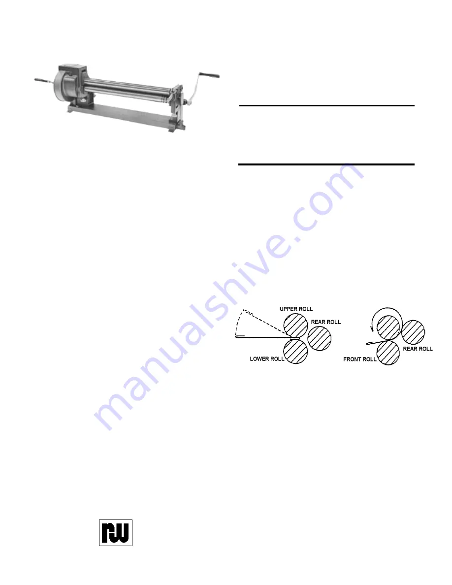
SLIP ROLL FORMERS 416, 417, 418
These machines are available in three different
sizes. All three models offer the standard front roll
drive. These units may be mounted directly to a
sturdy work bench or to an optional fabricated
pedestal, designed specifically for each unit.
MODEL
416
417
418
Capacity..........................ga. 16 16-18
18
Max Length.....................ins. 36
42
48
Roll Diameter..................ins. 3
3
3
Shipping Weight Boxed..lbs. 720
750
793
INSTRUCTIONS
CAUTION:
Be sure that the machine is securely bolted onto the pedestal or to the customer supplied
bench. Pedestal or work bench should be bolted to the floor.
1.
Adjust the Lower Roll to grip the metal firmly and evenly but without straining the machine. The
Lower Roll is adjusted up or down with the two lower Adjusting Screws .
2.
Adjust the Rear Roll to form the metal up as it travels through the rollers. The Rear Roll is adjusted
up or down with the two rear Adjusting Screws . Be sure the Rear Roll is parallel with the Lower
Roll. If the rolls are not parallel, the formed metal will be conical in shape instead of cylindrical.
3.
Feed the stock to the rolls only from the front.
4.
As the front rolls grip the stock, lift the rear end
of the metal upward. This will help reduce the
flat spot on the leading edge of the sheet and
will also cause the leading edge to pass over
the rear roll readily.
5.
The diameter of the formed cylinder is determined by the position of the Rear Roll. To increase
the diameter of a cylinder, lower the Rear Roll by turning the two rear Adjusting Screws
counter clockwise. To reduce the diameter of a formed cylinder, raise the Rear Roll by turning the
two rear Adjusting Screws clockwise. The two rear Adjusting Screws should be turned an equal
number of turns in order to keep the Rear Roll parallel with the front gripping rolls.
6.
To remove a cylindrical piece without distorting it, lift up the Locking Handle , raise the Right
Hand Housing Cap and turn the Cam Handle down. This raises the outboard end of the Upper
Roll and allows the formed cylinder to be slipped off of the Upper Roll.
7.
The Lower Roll and the Rear Roll have grooves of varying widths in one end. These are for the
purpose of accommodating a wired edge when forming a shape or when forming wire into a ring.
NO. 416
Summary of Contents for 416
Page 6: ...S h o p R P M a c h i n e 6 END VIEWS PartiallyAssembled SLIP ROLL FORMERS 416 417 418 ...
Page 7: ...S h o p R P M a c h i n e 7 END VIEW PartiallyAssembled SLIP ROLL FORMERS 416 417 418 ...
Page 8: ...S h o p R P M a c h i n e 8 END VIEWS PartiallyAssembled SLIP ROLL FORMERS 416 417 418 ...
Page 10: ...S h o p R P M a c h i n e 10 ...
Page 11: ...S h o p R P M a c h i n e 11 ...


