


603F9190-0L
INSTRUCTION MANUAL
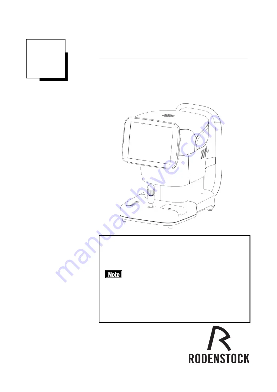
Specular Microscope
REM 4000
Read this manual thoroughly before using the instrument to
ensure proper and safe operation.
Contact Tomey Corporation or your local distributor if you
have any questions or encounter any issues during
operation.
■
Always follow the operation procedures
described in this manual.
■
Keep this manual in a readily accessible
location while operating the instrument.
■
Contact your local distributor if you lose this
manual.
Summary of Contents for REM 4000
Page 2: ......
Page 26: ...2 12 This page is intentionally left blank...
Page 33: ...3 7 Fig 1 Fig 2 2 1 3 4...
Page 82: ...3 56 This page is intentionally left blank...
Page 94: ...6 2 This page is intentionally left blank...
Page 101: ......


