background image


The RCB and MCB series user manual has been prepared  
by the Roal Electronics design team to assist qualified engineers 
in correctly implementing the products and to achieve the best reliability and performance. 

 
At time of print, the information contained in this document is believed to be correct and accurate. However, specifications are subject to change 
without prior notice and Roal Electronics will not be liable for any damage caused as a result of the information within this document. For 
continued product improvement, please report any errors contained in the document to Roal Electronics SpA. 


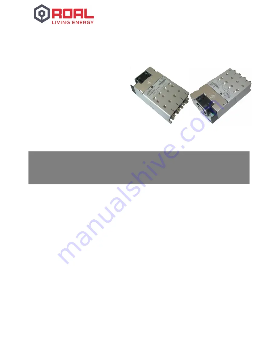
RCB600 and MCB600 series overview 


The RCB600 and MCB600 switch mode power supply series offers truly unrivalled power density, providing 600 W at 25 W/in

3


in a 5” x 3”x 1U package. They are the ultimate power solutions for system designers as they address the pressing demands 
for more power within less space. Providing multiple isolated outputs, the series carry full UL60601 (MCB600) and UL60950 2

nd


edition (RCB600) safety approvals. 

The basic system consists of an input module together with up to four fully isolated output modules, all supplied with advanced 
remote voltage and current programming functionality as standard.  

The input module delivers up to 600 W of output power and has 4 slots, each capable of separately delivering up to 150 W. A 
5 V, 200 mA medically isolated bias supply together with an AC mains signal (AC_OK) and a global inhibit signal (GINH) that 
can disable all outputs simultaneously, comes as standard on all models. 

A built in fan, which speed is automatically controlled, ensures the unit proper cooling in any operating condition maintaining 
at minimum fan RPM and, in turn, acoustic noise.   

Output modules are currently available in single output types with models covering voltage ranges from 1.5 V to 58 V and 
currents up to 25 A. All outputs can be connected in parallel or in a series resulting in a voltage range of up to 232 V and a 
maximum current of up to 100 A from a single chassis. 

By selecting the correct output modules, a custom power solution can be configured in a few minutes. This instantly available 
custom solution offers industry leading power density, total system efficiencies of up to 89% and suits all types of applications 
including industrial, medical, aerospace, military and telecoms. 

RCB600, MCB600 
User Manual


RCB600

 AND 

MCB600


S

ERIES 

O

VERVIEW


Summary of Contents for MCB600

Page 1: ...p to four fully isolated output modules all supplied with advanced remote voltage and current programming functionality as standard The input module delivers up to 600 W of output power and has 4 slots each capable of separately delivering up to 150 W A 5 V 200 mA medically isolated bias supply together with an AC mains signal AC_OK and a global inhibit signal GINH that can disable all outputs sim...

Page 2: ... operation 5 Input module operation 6 Signalling 9 Output module operation 11 Advanced output module features 14 Seriesed outputs 17 Outputs in parallel configuration 18 Mechanical dimensions and mounting 22 Connectors 23 Configuring your power supply 24 Safety 29 EMC compliance 27 Reliability 31 CONTENTS ...

Page 3: ...ing table contains all the characteristic parameter of each Output Module OP x and is a useful guide in identifying the optimal configuration for every application Output Module Nominal Voltage Rated current Voltage Adjustment Load Regulation Line Regulation OVP Output Power A 5 V 25 0 A 1 5 to 7 5 V 50 mV 0 1 VNOM 9 5 V 125 W B 12 V 15 A 4 5 to 15 V 100 mV 0 1 VNOM 18 V 150 W C 24 V 7 5 A 9 to 30...

Page 4: ...ng appropriately Avoid excessive back pressure in the general system or when using ducting to navigate hot air out of the system Earth terminal marking To comply with the requirements of UL60950 1 EN60950 1 IEC60950 1 CSA22 2 no 60950 1 UL60601 1 EN60601 1 IEC60601 1 CSA22 2 no 601 1 where the incoming wiring earth is intended for connection as the main protective earthing conductor and where the ...

Page 5: ...age also provides active input current limiting which prevents overloading of the input stage while maintaining high power factor The output of the PFC stage charges the hold up electrolytic capacitors which store enough energy to allow the system to continue operating during minor line disturbances These are the only electrolytic capacitors in the entire power supply and to further increase syste...

Page 6: ...ding loss of power The 5V bias supply will remain on for typically 100 ms after the output modules have turned off Hold up For short line disturbances 20 ms the output voltages will not be affected However the ACOK signal may still go low to warn that there is an impending loss of output power The ACOK signal will return to the high state once the unit has recovered from the disturbance Outputs th...

Page 7: ...Volt below 120 VRMS These de ratings can be calculated using the following conditional equations Equation for line de rating If Vin 120 VRMS Pout Prated Line de rating factor Prated 1 0 0083 120 Vin Otherwise Pout Prated Equation for temperature de rating If temp 50 C Pout Prated Temp derating factor Prated 1 Temp 50 0 025 Otherwise Pout Prated Depending on the application conditions one or both o...

Page 8: ... procedure outlined in the example below Example Estimate the efficiency of an RCB600 AABC at 160 VRMS input and 100 W load on each output 1 Define load efficiencies for each output module at specified load and 220 VRMS 2 Define change in efficiency from 220 VRMS to 160 VRMS for each output module 3 Sum the values from step one and two for each output module 4 Calculate the average efficiency for ...

Page 9: ...tly To ensure safety the following abnormal conditions may cause the entire unit to latch off which will disable the 5 V bias supply Over temperature of any part of the unit Over voltage on the output Internal over current device failure AC mains signal _ ACOK Output An ACOK signal is provided to indicate to the user that the AC mains voltage is applied and the input module is operating correctly ...

Page 10: ...tage set with the manual potentiometer Output Inhibits _ INH1 INH4 GINH Input The signals circuit provides four inhibit inputs to disable each output module individually and a fifth global inhibit input GINH to inhibit all modules simultaneously Each inhibit input is internally connected through an opto isolator to the respective output modules The basic internal electrical circuit and timing diag...

Page 11: ...the modules are protected against excessive output voltages This is implemented as a fixed voltage threshold VOVP in the table above and if the output voltage exceeds this threshold the entire power unit will be latched off To resume operation of the unit disconnect the AC input voltage for 2 minutes remove the faulty output module and reconnect the AC input voltage Note that no warning is given o...

Page 12: ...vailable peak power is a function of the output voltage and maximum current for each module Full peak power is only possible when the output voltage is adjusted to VMAX and the maximum current is drawn from the module Note that both average and peak power ratings are subject to the same temperature de rating as the input module de rate by 2 5 per C above 50 C but are not subject to any line de rat...

Page 13: ...ype Transient response The RCB MCB600 output modules have been especially designed to have high reliability and to achieve this all electrolytic capacitors have been eliminated from the design Due to this high dynamic load transients can cause relatively high voltage deviations at the output and although the outputs have a very high loop bandwidth with typical recovery times of less than 100 µs th...

Page 14: ...etermine the level of control voltage that will trigger OVP insert Vovp into the equation above Example VOVP 9 5 V Vset 5 V Vctrl 1 8 VOVP 0 6 Vset 0 66 V Hence Vctrl should never fall below 0 66 V otherwise OVP may latch the entire unit off Alternatively by manually adjusting the output voltage to less than 1 3 rd of the OVP voltage ensures that OVP can never be tripped by remote voltage control ...

Page 15: ... have no effect on the current limit When using an output module as a modulated current source the output voltage should be manually adjusted to the maximum that will be required by the application and this will be the upper voltage limit Once the load is connected the output current can then be modulated by applying a control voltage as described above Note that the power good threshold level is ...

Page 16: ...ge to the unit in each case An internal circuit measures the voltage between S to V and S to V when this voltage exceeds the thresholds specified in the datasheet the output voltage is reduced to benign levels During system design care must be taken to ensure power cables have a sufficiently low voltage drop at maximum load current to ensure this protection does not activate unintentionally In sys...

Page 17: ...ed outputs using the advanced V_control and I_control functions as described earlier However individual control of each module can be complex as the various control terminals are referenced to the positive output of the preceding module and require the use of multiple isolated control voltages to attain control over the full voltage range In practice individual control of each module is rarely req...

Page 18: ...ce When paralleled the outputs can operate in two distinct modes Normal parallel mode or Share parallel mode Normal parallel mode For normal parallel mode the positive power cables should be connected together and the negative power cables should be connected together No other connections are required as shown in the diagram below In this mode the highest adjusted output module will supply all of ...

Page 19: ... modules approximately 6 of the maximum rated current for each module The current output signal Ictrl can still be used to measure the output current but it must be scaled by N where N is the number of paralleled modules Paralleling across multiple chassis Paralleling across multiple chassis is not possible without external protection such as external diodes or controlled MOSFETs to prevent circul...

Page 20: ...ed diode or controlled MOSFET must be used on each output to prevent a device failure from causing a system failure However the diode introduces voltage drops between the supply and the load that significantly degrade the load regulation To counteract this the remote sense lines should be used to regulate the voltage at the load as shown below Typically this configuration can damage the internal s...

Page 21: ...her Remote voltage current programming can then be performed exactly as with a stand alone module It is not recommended to use remote voltage current programming in normal parallel mode WARNING Care must be taken to avoid differential voltages between the negative power output terminals of the paralleled modules as this can cause errors at the control pins To avoid this it is recommended that a lo...

Page 22: ...tration depth 4 00 mm max including chassis OUTPUT MODULES X 8 Screw type M3X5 C Sink Pozidriv Stainless steel Tightening torque Tighten to 0 75 Nm Penetration depth Defined by screw CHASSIS X 2 Screw type M3X5 C Sink Pozidriv Stainless steel Tightening torque Tighten to 0 75 Nm Penetration depth Defined by screw CHASSIS X 2 Screw type M2 5X4 C Sink Pozidriv Stainless steel Tightening torque Tight...

Page 23: ... tin finish or any direct equivalent Molex 0010013036 0008701031 Power Unit Signal J2 2 00 mm 0 079 in 12 circuits housing with locking ramp or any direct equivalent Crimp terminal 24 30 AWG gold finish or any direct equivalent Molex 0511101260 0503948051 Output Power J3 J4 Quick Disconnect Receptacle compatible with PCB mounting TAB size 0 80X6 35 mm Tin finish Vogt AG Tyco Electronics NA 3967 64...

Page 24: ...nection and all other connections from the power supply Remove the unit from the system where it could be applied WARNINGS Leave the unit to stand for a minimum of 3 minutes after removing all power and other connections from the unit before attempting to configure or re configure the power supply Always remove the power supply before handling During operation the external surface of the unit can ...

Page 25: ... supply only remove the screws that hold an OP while living tightened BP s ones Step 4 Removed all the screws that hold the OPs the next step involves opening the lid by rotating it around the two pivots that bind it to the chassis Ensure that all the output modules are loose from the lid before doing so Once the cover has been rotated at the most comfortable angle it is possible to remove any BPs...

Page 26: ...eplace or install new OPs a 15 pins header must be plugged directly into the mating connector on the unit printed circuit board PCB To do so simply align the connector and push the OP properly down securing it in the notch at the back of the chassis as shown below Each connector is keyed to prevent improper insertion Step 4 Once the modules are replaced and the new configuration is complete the li...

Page 27: ...to the lid before closing it To facilitate operations the BPs should be assembled before the OPs As evidence of power unit proper closing output modules PCBs must be properly housed in the notches and in the slots of the chassis and cover respectively mechanical parts and screws holes must be aligned without exerting any effort ...

Page 28: ... It is sealed by a tamper evident security label Removing it makes accessible high voltage parts exposing a operator to electric shock danger Any alteration affecting the label will void the warranty on the Power Supply Step 6 Reconnect the AC line input and apply power to ensure all the output modules are working by checking their LED light comes on Always check the output voltage of each module ...

Page 29: ...er must provide additional and adequate protection to service and technical personnel Always remove the power before handling the unit During operation the external surface of the unit can become hot Leave to stand for 10 minutes to allow the unit to cool down before handling it Dangerous voltages are present within the power supply Covers may only be removed by qualified personnel when the power ...

Page 30: ...put and output cables should be separated as much as possible Output power and sense cables should be twisted pairs and routed parallel to each other Do not twist sense and power cables together All cables lengths and loop areas should be minimised Where cables must enter or exit the enclosure good high frequency 100 nF decoupling capacitors of sufficient voltage rating should be connected to the ...

Page 31: ... Electronics S p A assumes no liability from the use of its products outside of specifications No license is granted to any intellectual property rights by this document ROAL ELECTRONICS S P A DISCLAIMS ALL REPRESENTATIONS AND WARRANTIES OF ANY KIND EXPRESS OR IMPLIED INCLUDING BUT NOT LIMITED TO IMPLIED WARRANTIES OF NONINFRINGEMENT MERCHANTABILITY AND FITNESS FOR A PARTICULAR PURPOSE Eu and RoW ...

Reviews: