


User‘s Guide
OUTPUT 29
OUTPUT 30
OUTPUT 31
OUTPUT 32
OUTPUT 25
OUTPUT 26
OUTPUT 27
OUTPUT 28
OUTPUT 21
OUTPUT 22
OUTPUT 23
OUTPUT 24
OUTPUT 17
OUTPUT 18
OUTPUT 19
OUTPUT 20
OUTPUT 13
OUTPUT 14
OUTPUT 15
OUTPUT 16
OUTPUT 9
OUTPUT 10
OUTPUT 11
OUTPUT 12
OUTPUT 5
OUTPUT 6
OUTPUT 7
OUTPUT 8
OUTPUT 1
OUTPUT 2
OUTPUT 3
OUTPUT 4
29
30
31
32
25
26
27
28
21
22
23
24
17
18
19
20
13
14
15
16
9
10
11
12
5
6
7
8
1
2
3
4
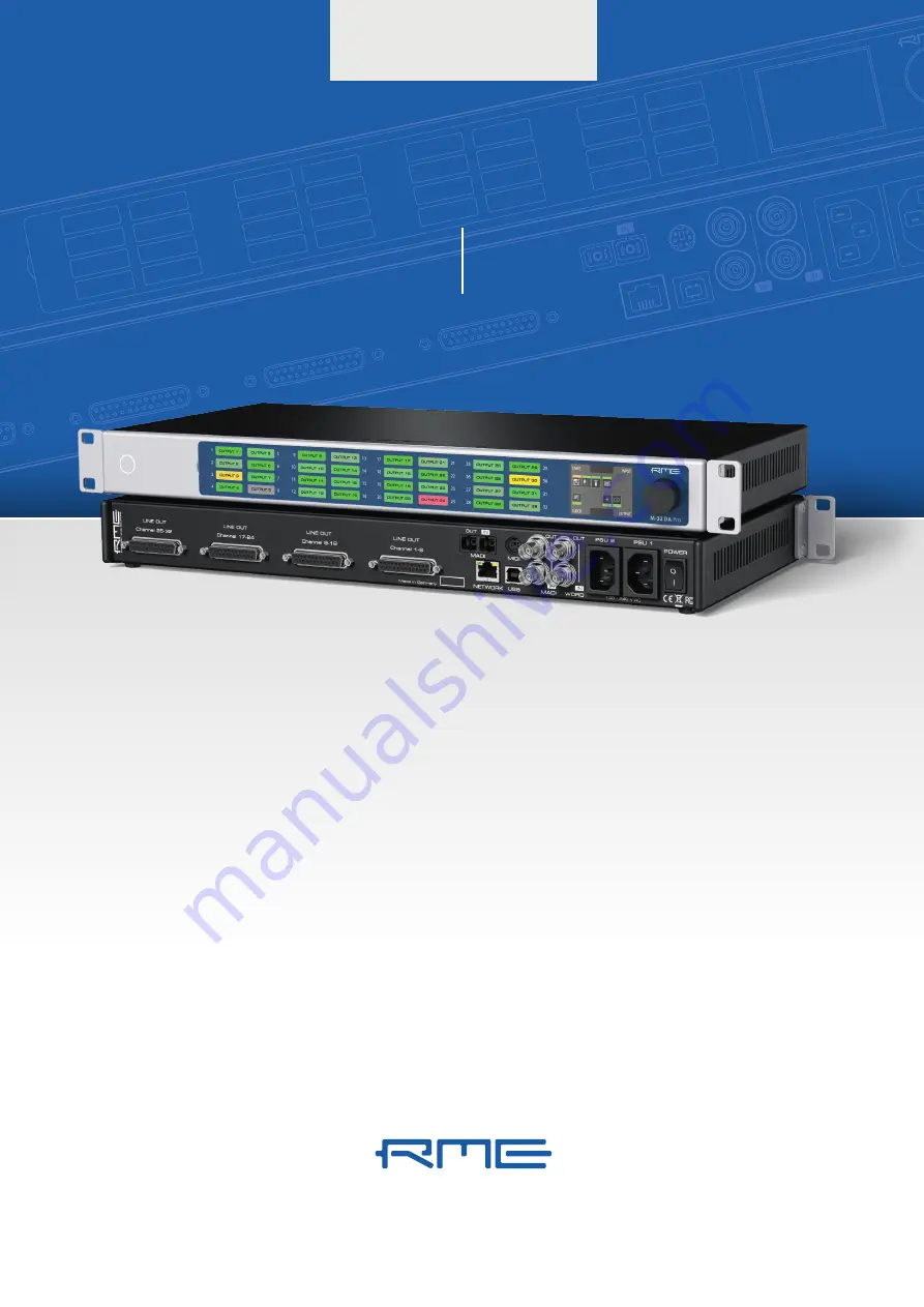
M-32 D
A Pro
NETWORK
MADI
WORD
Channel 17-24
LINE OUT
LINE OUT
LINE OUT
Channel 8-16
Channel 1-8
OUT
OUT
OUT
PSU 2
PSU 1
MADI
USB
MIDI
M-32
DA Pro
32-Channel 192 kHz D/A Converter
with MADI & AVB I/O
High-end
Converter


