background image

©2009 Alamo Group Inc.

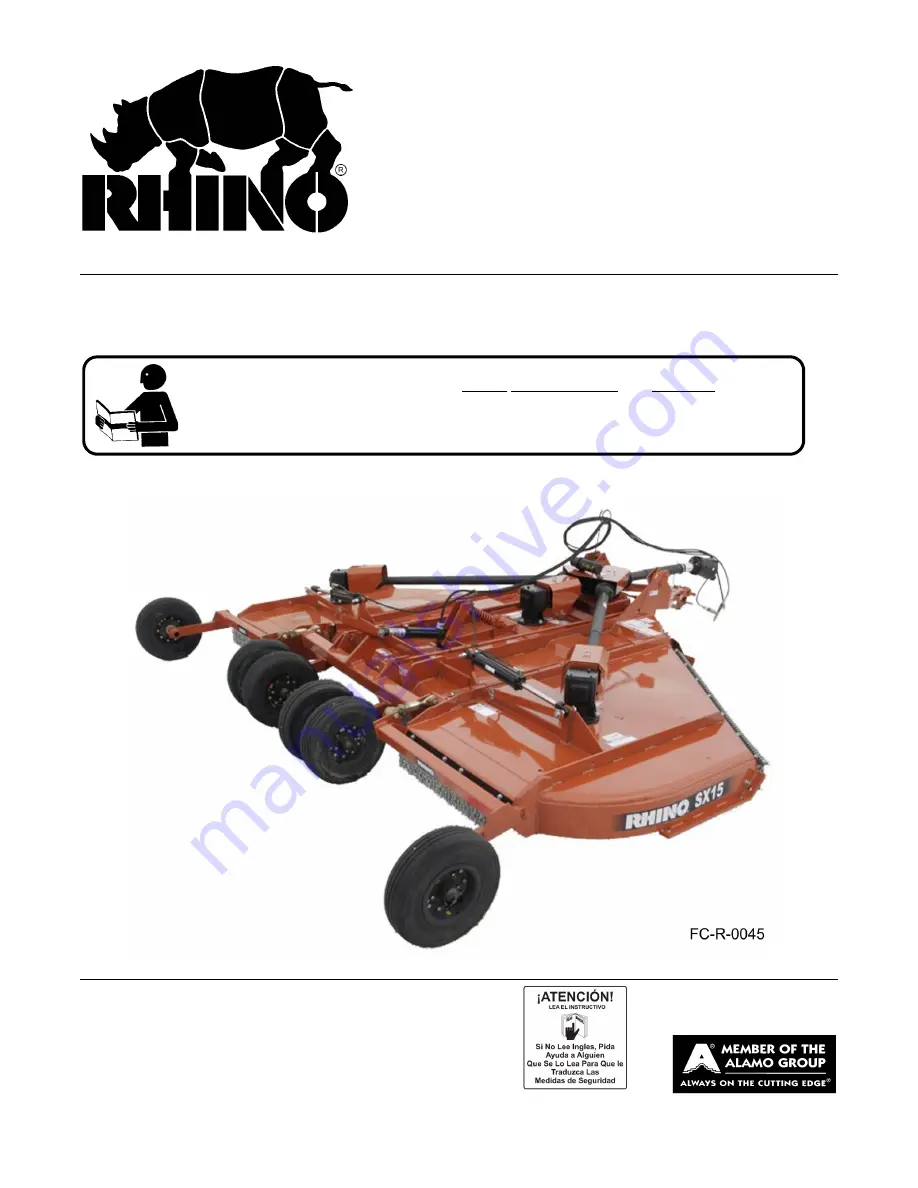
SX15

Published 01/09

      Part NO. 00786228C

OPERATOR’S MANUAL 

RHINO

®


1020 S. Sangamon Ave.
Gibson City, IL 60936
800-446-5158
Email: [email protected]

FLEX-WING MECHANICAL LEVEL

LIFT ROTARY MOWER

This Operator's Manual is an integral part of the safe operation of this machine and must 
be maintained with the unit at all times.  READ, UNDERSTAND, and FOLLOW the Safety 
and Operation Instructions contained in this manual before operating the equipment. 

C01-

Cover

$0.00

Summary of Contents for SX15

Page 1: ...Email parts servis rhino com FLEX WING MECHANICAL LEVEL LIFT ROTARY MOWER This Operator s Manual is an integral part of the safe operation of this machine and must be maintained with the unit at all times READ UNDERSTAND and FOLLOW the Safety and Operation Instructions contained in this manual before operating the equipment C01 Cover 0 00 ...

Page 2: ...safety equipment properly attached to minimize the chance of acci dents BEFORE YOU START Read the safety messages on the implement and shown in your manual Observe the rules of safety and common sense WARRANTY INFORMATION Read and understand the complete Warranty Statement found in this Manual Fill out the Warranty Registration Form in full and return it to within 30 Days Make certain the Serial N...

Page 3: ...own this video and presented you a DVD Video when you purchased your mower If you or any mower operator have not seen this video Watch the Video Read this Operator s Manual and Complete the Video Guidebook before operating your new mower If you do not understand any of the instructions included in the video or operator s manual or if you have any questions concerning safety of operation contact yo...

Page 4: ...MA Mower Operator Safety Video Mower Operator s Manual AEM Mower Operator s Safety Manual Requester Name Phone Requester Address City State Zip Code Mower Model Serial Number Date Purchased DealerSalesperson Dealership Name DealershipLocation Mail to AEM Video Services 1502 E Walnut street Seguin TX 78155 Or Fax to 830 372 9529 Or Email to AEMVideo alamo group com ...

Page 5: ...ndard Equipment CHAINGUARDS OPTIONAL EQUIPMENT 3 6 FRONT AND REAR DEFLECTORS Standard Equipment CHAINGUARDS OPTIONAL EQUIPMENT 3 7 HYDRAULIC SYSTEM ASSEMBLY 3 7 HYDRAULIC THREE SPOOL VALVE ACCESSORY EXTRA EQUIPMENT 3 8 WINCH AND STAND ACCESSORY 3 9 OPERATION SECTION 4 1 Standard Equipment and Specifications 4 3 OPERATOR REQUIREMENTS 4 4 TRACTOR REQUIREMENTS 4 5 ROPS and Seat Belt 4 5 Tractor Safet...

Page 6: ...d 4 34 Operating the Mower 4 34 Shutting Down the Implement 4 37 DISCONNECTING THE MOWER FROM THE TRACTOR 4 37 MOWER STORAGE 4 39 TRANSPORTING THE TRACTOR AND IMPLEMENT 4 39 Tire and Wheels 4 41 Transporting on Public Roadways 4 41 Hauling the Tractor and Implement 4 43 TROUBLESHOOTING GUIDE 4 45 MAINTENANCE SECTION 5 1 Lubrication 5 2 DRIVELINES 5 4 MAIN CV DRIVELINE SAFETY SHIELD 5 5 WING GEARBO...

Page 7: ...Safety Section 1 1 2009 Alamo Group Inc SAFETY SECTION ...

Page 8: ...re intended to warn the owner operator of impending hazards and the degree of possible injury faced when operating this equipment Indicates an imminently hazardous situation that if not avoided WILL result in DEATH OR VERY SERIOUS INJURY Indicates an imminently hazardous situation that if not avoided COULD result in DEATH OR SERIOUS INJURY Indicates an imminently hazardous situation that if not av...

Page 9: ... operator should remain in his seat for 60 seconds after the brake has been set the PTO disengaged the tractor turned off and all evidence of rotation has ceased S3PT 10 Wait a minute Save a life Never crawl under a raised Implement supported solely by the Tractor 3 Point hitch Release of the control lever or mechanical failure will result in the Implement falling and possible injury or death Alwa...

Page 10: ... around Tractor or Implement Children can slip or fall off the Equipment and be injured or killed Children can cause the Implement to shift or fall crushing themselves or others SG 25 NEVER use drugs or alcohol immediately before or while operating the Tractor and Implement Drugs and alcohol will affect an operator s alertness and coordination and therefore affect the operator s ability to operate...

Page 11: ...he engine or muffler Use gloves and eye protection when servicing hot components Contact with a hot surface or fluid can cause serious injury from burns or scalding SG 38 Repeated or substantial breathing of hazardous dusts including crystalline silica could cause fatal or serious respiratory disease including silicosis Concrete masonry many types of rock and various other materials contain silica...

Page 12: ...to or striking sign posts guard rails concrete abutments or other solid objects Such an impact could cause the Implement and Tractor to pivot violently resulting in loss of steering control serious injury or even death Never allow the Implement to contact obstacles S3PT 12 Be sure you have adequate knowledge of the property you will be working on Take time to make yourself aware of any area underg...

Page 13: ...actor and Implement and are physically large enough to reach and operate the controls easily SG 11 Do not mount or dismount the Tractor while the tractor is moving Mount the Tractor only when the Tractor and all moving parts are completely stopped SG 12 Start tractor only when properly seated in the Tractor seat Starting a tractor in gear can result in injury or death Read the Tractor operators ma...

Page 14: ...cts from entering If a tractor cab is not available wear suitable clothing including head face and hand protection to shield you from the insects Attacking insects can cause you to lose control of the tractor which can result in serious injury or death to you or bystanders Never dismount a moving tractor SG 40 Mow only in conditions where you have clear visibility in daylight or with adequate arti...

Page 15: ...chains can become entangled in the operating parts of the mower head These items could then swing outside the housing at greater velocities than the blades Such a situation is extremely hazardous and could result in serious injury or even death Inspect the cutting area for such objects before mowing Remove any like object from the site Never allow the cutting blades to contact such items SGM 06 Mo...

Page 16: ...see Mower Standard Equipment and Specifications DO NOT use this mower to cut vegetation above the Mower s rated capacity or to cut any type of non vegetative material Only operate this Mower on a properly sized and equipped Tractor Operating this Mower in an application for which it is not designed and or operating the Mower with the wrong size Tractor can cause Mower component damage and equipmen...

Page 17: ...ing removed and mowed again at desired final height This will also reduce power required to mow reduce wear and tear on the Mower drivetrain spread cut material better reduce streaking and make the final cut more uniform SRM 01 Do Not attempt to raise or lower the implement wing unless the Implement tongue is securely attached to the Tractor drawbar The Implement could tip over and cause equipment...

Page 18: ...ment S3PT 17 Before operating the Implement check to make sure the Implement input driveline will not bottom out or become disengaged Bottoming out occurs when the inner shaft penetrates the outer housing until the assembly becomes solid it can shorten no more Bottoming out can cause serious damage to the Tractor PTO by pushing the PTO into the Tractor and through the support bearings or downward ...

Page 19: ...ment can be operated at a higher speed Use extreme care and reduce your speed when turning sharply to prevent the tractor and implement from turning over Determine the maximum turning speed for you and this equipment before operating on roads or uneven ground Only transport the Tractor and Implement at the speeds which allow you to properly control the equipment Be aware of the operating condition...

Page 20: ... Implement behind a properly sized and equipped Tractor which exceeds the weight of the Implement by at least 20 DO NOT tow the Implement behind a truck or other type of vehicle Never tow the Implement and another Implement connected in tandem Never tow the Implement at speeds over 20 MPH STI 06 Secure the Implement for transport before traveling on public roads For pull type Implements secure the...

Page 21: ...veline connected and running Rotating Parts Blades or Drivelines could turn without warning and cause immediate entanglement injury or death S3PT 11 Never interfere with factory set hydraulic calibrations Any change in calibration could cause a failure of the equipment and may result in injury SBH 13 Always maintain the safety signs in good readable condition If the safety signs are missing damage...

Page 22: ...h have sharp edges Sharp surfaces can inflict severe laceration injuries if proper hand protection is not worn SG 37 All Safety Shields Guards and Safety devices including but not limited to the Deflectors Chain Guards Steel Guards Gearbox Shields PTO integral shields and Retractable Door Shields should be used and maintained in good working condition All safety devices should be inspected careful...

Page 23: ...yourself aware of any area underground lines or cables Contact with buried lines or cable could result in serious injury or death STL 1 In wet conditions where there is a likelihood of material collecting on the Implement make certain that this material is removed before traveling on public roadways STL 7 To prevent tipping of Implement when stored in folded position use carrying wheels or adequat...

Page 24: ...mote safe operation Damage to the decals may occur while in shipping use or reconditioning Rhino cares about the safety of its customers operators and bystanders and will replace the safety decals on this product in the field free of charge Some shipping and handling charges may apply Contact your Rhino dealer to order replacement decals ...

Page 25: ... 1 INSTRUCT CW Blade Rotation 11 03200347 1 REFLECT SMV 12 1458392 2 REFLECT Red Reflector 13 1458393 1 REFLECT Amber Reflector 14 D302 4 LOGO Rhino Logo 4x6 15 D303 2 LOGO Rhino Logo 4x16 16 00786231 2 NAME SX 15 Large 17 99102 2 NAME Rhino Name Logo 18 00786230 1 NAME SX 15 Small 19 00760657 1 IMPORTANT Genuine Rhino Parts 20 nfs 1 SERIAL PLATE Serial Number Plate 21 00776031 1 INSTRUCT Canister...

Page 26: ...SAFETY SX15 01 09 Safety Section 1 20 2009 Alamo Group Inc SAFETY Decal Description Multi Hazard Decal Sheet P N D389 Decal D389 consists of the following multi hazards ...

Page 27: ...SAFETY SX15 01 09 Safety Section 1 21 2009 Alamo Group Inc SAFETY Multi Hazard Decal Sheet P N D390 Decal D390 consists of the following multi hazards ...

Page 28: ...SAFETY SX15 01 09 Safety Section 1 22 2009 Alamo Group Inc SAFETY Driveline Hazards P N D388 Decal D388 consists of the following multi hazards ...

Page 29: ... blades in pairs P N D395 DANGER Stay clear when lowering or raising wings P N 00753840 DANGER Guard Missing Do Not Operate If you see this decal Do Not Operate the mower until the shield has been replaced P N 00756004 DANGER Rotating Driveline Keep Away Contact can cause death P N 00756005 ...

Page 30: ...ection 1 24 2009 Alamo Group Inc SAFETY INFORMATION 5 Year Gearbox Warranty P N 00771283 WARNING Avoid Bodily Injury Use 540RPM PTO Speed Only P N D103 Blade Rotation Counter Clockwise P N D137 Blade Rotation Clockwise P N D138 ...

Page 31: ...w Moving Vehicle Decal Keep SMV reflector clean and visible DO NOT transport or operate without the SMV P N 03200347 Red Reflector Keep reflectors clean and visible P N 1458392 Amber Reflector Keep reflectors clean and visible P N 1458393 Logo Product Name Rhino P N D302 ...

Page 32: ...SAFETY SX15 01 09 Safety Section 1 26 2009 Alamo Group Inc SAFETY P N D303 Logo Product Name Rhino P N 00786231 LOGO MODEL NAME SX15 Logo Product Name Rhino P N 99102 P N 00786230 LOGO MODEL NAME SX15 ...

Page 33: ... RHINO replacement parts P N 00760657 Read Operator s Manual The operator s manual is located inside this canister If the manual is missing order one from your dealer P N 00776031 WARNING Jack Maximum Capacity 3 200 lbs Side Load 2 000 lbs P N D482 WARNING Explosion Hazard Release all air pressure in tire before loosening bolts P N 1006348 ...

Page 34: ...operation and servicing of all equipment with which the employee is or will be involved Employer Responsibilities To ensure employee safety during Tractor and Implement operation it is the employer s responsibility to 1 Train the employee in the proper and safe operation of the Tractor and Implement 2 Require that the employee read and fully understand the Tractor and Implement Operator s manual 3...

Page 35: ......

Page 36: ......

Page 37: ......

Page 38: ......

Page 39: ......

Page 40: ......

Page 41: ......

Page 42: ......

Page 43: ......

Page 44: ......

Page 45: ......

Page 46: ......

Page 47: ......

Page 48: ......

Page 49: ......

Page 50: ......

Page 51: ......

Page 52: ......

Page 53: ......

Page 54: ......

Page 55: ......

Page 56: ......

Page 57: ......

Page 58: ......

Page 59: ......

Page 60: ......

Page 61: ......

Page 62: ......

Page 63: ......

Page 64: ......

Page 65: ......

Page 66: ......

Page 67: ......

Page 68: ......

Page 69: ......

Page 70: ......

Page 71: ......

Page 72: ......

Page 73: ......

Page 74: ......

Page 75: ......

Page 76: ......

Page 77: ......

Page 78: ......

Page 79: ...Introduction Section 2 1 2009 Alamo Group Inc INTRODUCTION SECTION ...

Page 80: ... Signal Word as seen below is intended to warn the owner operator of impending hazards and the degree of possible injury faced when operating this machine Rhino typically offers three types of shielding to protect the operator passerby livestock and property from thrown objects deflectors single chain guards and double chainguard Shielding should be selected based on the intended use of the mower ...

Page 81: ...Tongue attaching Plate on the center Mainframe section Chain Guards are extra equipment Deflectors Driveline Integral Shields and Gearbox Shields are standard equipment and are to be used at all times To place the warranty into effect fill out the warranty card in full giving all the requested information and mail promptly Be sure to give the serial number of this Mower For Non Agricultural use OS...

Page 82: ...actor and implement 2 Fill out the Warranty Card in full Be sure to answer all questions including the Serial Number of the implement Mail within 30 days of delivery date of this implement NOTE Warranties are honored only if completed Owner Registration and Warranty forms are received by Alamo Group within thirty days of delivery of the implement 3 Record the Mower Model and Serial Numbers on the ...

Page 83: ...Assembly Section 3 1 2009 Alamo Group Inc ASSEMBLY SECTION ...

Page 84: ...ore tightening hardware Refer to chart on page 5 8 for proper torque All bolts are Grade 5 unless otherwise specified 1 Position center section on flat surface Elevate approximately 10 inches from ground to permit the installation of wings Support the frame securely at enough points so that there is no danger of it falling during assembly causing injury to persons or damage to the cutter 2 Install...

Page 85: ...1 2 x 1 1 4 bolt 3 and tighten nut 4 FIGURE Mnt R 0170 4 Install Center Axle Legs 1or 2 and Outer Axle 16 to Center Axle 2 using 3 4 x 4 bolts 18 and lock nuts 7 Tighten securely NOTE Install bolts through flats on Axle tube 6 and through gauge wheel Axle Legs 1or 5 and then Center Axle 2 Attach the adjustment Turnbuckle to the Outer Axle 6 and Wing Axle using flatwashers 10 and cotter pins 8 Atta...

Page 86: ...istance such as mechanical assistance two people and proper lifting techniques when connecting or installing the driveshaft to reduce the possibility of back injuries 7 Install Center Divider Gearbox Shield Remove the top two bolts and lockwashers from the Center Gearbox Install the shield on the Center Divider Gearbox and replace with longer hardware 8 Install opposite end of Wing Driveline to ou...

Page 87: ...Lift Cylinder with base end attached to Spring Support Note See hydraulic schematic for more details 10 Install Transports Bars on lower Cylinder Pin and retain using cotter pin Install Transport Bar over pin welded to wing frame to store when not in use 11 Check oil levels in all boxes Add lube if required ...

Page 88: ...ssigned agricultural task DEFLECTORS Front and rear Deflectors Standard Equipment are recommended for the average user and will provide superior protection from thrown objects with proper operation under normal conditions Deflectors must be maintained in good repair or replace after no more than two inches of wear off lower edge Fasten the front Rubber Deflector FIGURE 7 to the Center Section and ...

Page 89: ...s 4 HYDRAULIC SYSTEM ASSEMBLY 1 This unit can be operated on any tractor which has at least two remote outlets IMPORTANT Remote outlets connected to wings cylinders must have a float detent position on the control lever If not the tractor must be equipped with an external valve bank which has float detent positions 2 If tractor has only two outlets one must be used to control the center axle and t...

Page 90: ...tem there is no relief valve provided When the oil flow is blocked and there is no relief valve the pump either stops breaks a hose is blown or the engine stalls Hose failure or a pump shaft failure is most common If an open center valve containing a relief valve is installed in a closed center system the pump cut off pressure over 2200 psi will exceed that of the relief valve and pump oil continu...

Page 91: ...Alamo Group Inc ASSEMBLY WINCH AND STAND ACCESSORY Install Mounting Bracket 1 onto left rear side of Center Section Install 5 8 x 1 1 2 bolts and locknuts through holes in frame to retain bracket FIGURE Asm R 0181 Holes must be drilled through Deck ...

Page 92: ......

Page 93: ...Operation Section 4 1 2009 Alamo Group Inc OPERATION SECTION ...

Page 94: ...xplaining the operation of a rotary mower and are not necessarily of a SX15 cutter Some pictures may show shields removed for purposes of clarity NEVER OPERATE this implement without all shields in place and in good operational condition The operator must be familiar with the mower and tractor operation and all associated safety practices before operating the mower and tractor Proper operation of ...

Page 95: ...Stand Std Overall Width 187 Blade Overlap 6 Transport Width 96 Wing Lift Hyd Std Wing Flex Degrees 90 Degrees Up 22 Degrees Down Replaceable Skid Shoe Std Ratings based on actual field performance The Mower is designed for certain mowing applications and is rated to cut up to a specific size vegetation see Mower Standard Equipment and Specifications DO NOT use this mower to cut vegetation above th...

Page 96: ...Protective Equipment PPE for the job conditions when attaching operating servicing and repairing the equipment PPE is designed to provide operator protection and includes the following safety wear PERSONAL PROTECTIVE EQUIPMENT PPE Protective Eye Glasses Goggles or Face Shield Hard Hat Steel Toe Safety Footwear Gloves Hearing Protection Close Fitting Clothing Respirator or Filter Mask depends on op...

Page 97: ...ed with a Roll Over Protective Structure ROPS tractor cab or roll bar and seat belt to protect the operator from falling off the tractor especially during a roll over where the driver could be crushed and killed Only operate the tractor with the ROPS in the raised position and seat belt fastened Tractor model not equipped with a ROPS and seat belt should have these life saving features installed b...

Page 98: ...ust be maintained on the tractor front end at all times Front end weight is critical to maintain steering control and to prevent the tractor from rearing up while driving If the front end is too light add weight until a minimum of 20 total weight is reached on the front tires Front weights and weight carriers can be purchased through an authorized tractor dealership OPS U 0005 3 4 Drawbar The trac...

Page 99: ...on matching Implement driveline to a Tractor PTO Use of an adapter can double the operating speed of the Implement resulting in excessive vibration thrown objects and blade and implement failure Adapter use will also change the working length of the driveline exposing unshielded driveline areas Serious bodily injury and or equipment failure can result from using a PTO adapter Consult an authorized...

Page 100: ...ever allow children to operate ride on or come close to the Tractor or Implement Usually 16 17 year old children who are mature and responsible can operate the implement with adult supervision if they have read and understand the Operator s Manuals been trained in proper operation of the tractor and Implement and are physically large enough to reach and operate the controls easily SG 11 Never allo...

Page 101: ...position The hydraulic remote control levers are in the neutral position The tractor transmission levers are in park or neutral Refer to the tractor owner s manual for tractor starting procedures Only start the tractor while seated and belted in the tractor operator s seat Never bypass the ignition switch by short circuiting the starter solenoid After the tractor engine is running avoid accidental...

Page 102: ... attach the mower safety chain to the tractor drawbar or drawbar support frame 6 Lower the jack until the tongue is completely supported by the drawbar Remove jack from the tongue and place on storage bracket of mower Safety Tow Chain If the mower is towed on a public roadway a safety chain with tensile strength equal to or greater than the gross weight of the mower must be connected between the t...

Page 103: ...rate the wings must be plumbed together and will be controlled using one hydraulic control valve and the center section with the remaining control valve Ensure that the operator is aware that each wing cannot be controlled independently nor will they raise and lower simultaneously Operating the Mower Hydraulics with a 3 Spool Hydraulic Control Valve Extra Equipment Ensure the valve matches the hyd...

Page 104: ...lower than the rear 3 Shut down the tractor place the transmission in park and set the parking brake before dismounting 4 Level the mower deck front to rear by adjusting the leveling rods linking the tongue to the rear axle DO NOT allow feet or other body part underneath the mower when making adjustments To adjust rod length loosen jamnut and screw turnbuckles To lower the front lengthen the rods ...

Page 105: ...r wings are leveled retighten jamnuts to maintain settings 7 2 Setting Deck Pitch To facilitate safe and efficient operation the mower should be operated with the deck approximately 3 4 LOWER IN THE FRONT THAN THE REAR Operating the mower at this pitch will allow the mower to cut the grass only once and requires less work from the tractor In addition a more even distribution of the clippings from ...

Page 106: ...aft release the locking collar and position the yoke until the locking collar balls are seated onto the PTO shaft Push and pull the driveline back and forth several times to ensure a secure attachment OPS R 0003_A When attaching the Implement input driveline to the Tractor PTO it is important that the connecting yoke spring activated locking collar slides freely and the locking balls are seated se...

Page 107: ...act your local dealer or Technical Service for proper directions OPS R 0004_J Engagement Check Procedure With the driveline attached position the mower to the point where the telescoping driveline is at its maximum extension Completely shut down the tractor and secure in position Mark the inner driveline shield 1 8 from the end of the outer shield Disconnect the driveline from the tractor and sepa...

Page 108: ... a hard left turn until there is approximately a 1 clearance between the left rear tractor tire and mower frame or tongue Stop and completely shut down the tractor Place the tractor in Park and apply the Parking Brake before dismounting Check the CV joint at this maximum turning radius by holding the driveline yoke above the PTO shaft and then angle the CV joint to its maximum angle A minimum diff...

Page 109: ...e pre operation inspection reveals any condition affecting safe operation Perform repairs and replacement of damaged and missing parts as soon as noticed By performing a thorough pre operation inspection and service valuable down time and repair cost can be avoided OPS U 0029 Always disconnect the main PTO Driveline from the Tractor before performing service on the Implement Never work on the Impl...

Page 110: ...ke fluid level Power steering fluid level Fuel condition and level Sufficient lubrication at all lube points Air filter condition OPS U 0030 9 2 Mower Pre Operation Inspection Service Before each mower use a complete inspection and service is required to ensure the mower is in a good and safe working condition Damaged and or broken parts should be repaired and or replaced immediately To ensure the...

Page 111: ...tion and not damaged Replace worn broken and missing sections immediately Ensure the driveline integral shields are in good condition and rotate freely Inspect that all bolts and screws are in position and are properly torqued OPS R 0009 All Safety Shields Guards and Safety devices including but not limited to the Deflectors Chain Guards Steel Guards Gearbox Shields PTO integral shields and Retrac...

Page 112: ...ntenance section Inspect each gearbox oil level using dipstick level indicator and replenish if needed A low oil level is a warning sign that the gearbox may be cracked or its seal is damaged and needs to be replaced Ensure all gearbox vents are in place and free from clogs OPS R 0011_D Inspect blades and blade bolts for looseness and excessive wear Make sure the mower is securely blocked up befor...

Page 113: ... leaks on the cylinders along the hydraulic lines and at tractor hydraulic ports IMPORTANT DO NOT use your hands to check for oil leaks Use a piece of heavy paper or cardboard to check for hydraulic oil leaks OPS R 0013 Ensure that the mower is equipped and secured with wing brace supports Check the condition of the wing hinge pins Check the condition of the mower axle suspension spring Inspect mo...

Page 114: ...r REPLACE BOTH BLADES on that carrier IMMEDIATELY if either blade has Become bent or deformed from it s original shape or Any cracks are visible or Deep gouges in the blade s surface are persent or Gouges or chipped areas in the cutting edge are larger than 1 2 12 7mm or The material on the leading edge has been worn away by more than 1 2 12 7mm Failure to replace abnormally worn blades may lead t...

Page 115: ... BOLTS on the Blades IMMEDIATELY if either blade bolts has Visible cracks or If the recessed area on blade bolt is worn off or If Blade Bolt has gouges or chipped areas Failure to replace abnormally worn blade bolts may lead to catastrophic failure of the blades and ejection of the broken part which may cause serious bodily injury or death Always replace Blade Bolts with new bolts whenever replaci...

Page 116: ...ety decals are in place and legible The tongue hitch connection bolts pins are tight There are no cracks in tongue or hitch The tow chain is secured to the tractor mower The hydraulic cylinders pins are tight There are no leaking or damaged hoses The mower deck is clear of cut grass and debris Chain guards deflectors are in place in good condition Driveline gearbox shields are in good condition Dr...

Page 117: ...g lights function properly The SMV Sign is clean and visible The tires are in good condition with proper pressure The wheel lug bolts are tight The tractor brakes are in good condition The steering linkage is in good condition There are no visible oil leaks The hydraulic controls function properly The ROPS or ROBS Cab is in good condition The seatbelt is in place and in good condition The 3 point ...

Page 118: ...s for you and the equipment Make sure you abide by the following rules Test the tractor at a slow speed and increase the speed slowly Apply the Brakes smoothly to determine the stopping characteristics of the Tractor and Implement As you increase the speed of the Tractor the stopping distance increases Determine the maximum transport speed not to exceed 20 mph 30 kph for transporting this equipmen...

Page 119: ...or limit the tractor from turning During normal cutting conditions locking the differential provides no benefit and should not be used OPS U 0013 Be aware of the operating conditions Do not operate the Tractor with weak or faulty brakes When operating down a hill or on wet or rain slick roads the braking distance increases use extreme care and reduce your speed in these conditions When operating i...

Page 120: ... When transporting only raise the center section high enough to clear ground obstacles OPS R 0016 Operating Position To lower the wings remove the transport lock braces and secure braces on storage bracket DO NOT drive out transport brace pins The wing cylinder may need to be retracted to remove tension for brace removal After removing brace bars extend wing hydraulic cylinders and fully lower win...

Page 121: ... control lever in the transport detent position to prevent damage to the mower driveline and tongue when turning Perform turns with the tractor and mower at slow speeds to determine how the tractor with an attached mower handles a turn Determine the safe speed to maintain proper control of the tractor when making turns When turning with a towed implement the overall working length of the unit is i...

Page 122: ... the support bearings or downward onto the PTO shaft breaking it off Damage resulting from over collapse of the driveline s inner profile and its outer housing may allow the driveline to come loose from the Tractor which could cause bodily injury to the operator or bystanders and or extensive damage to the Tractor or Implement OPS R 0020 NOTE See Section 7 1 Driveline Length Check and Bottoming Ou...

Page 123: ...TRACTOR AND IMPLEMENT AND ALL CONTROLS BEFORE ATTEMPTING TO OPERATE The operator must read and understand the Safety and Operation Sections of the implement and tractor operator s manuals These manuals must be read and explained to any operator who cannot read Never allow someone to operate the implement and tractor without complete operating instructions Before starting any operation the operator...

Page 124: ...once Immediately idle the engine speed and disengage the PTO Wait for all mower rotating motion to stop then raise the mower and move the tractor and implement off the object Inspect the area and remove or mark the location of the debris Inspect the condition of the mower and make any needed repairs immediately Make sure the blades are not damaged and the carrier is balanced before resuming operat...

Page 125: ...n spread cut material better reduce streaking and make the final cut more uniform SRM 01 11 3 Engaging the Power Take Off PTO Before engaging the PTO make certain that the area is clear of bystanders and passersby The implement must be completely lowered and the deck positioned at a safe operating height NEVER engage the PTO with the implement in the raised position Set the tractor engine speed at...

Page 126: ...ontrol the tractor and mower The correct mowing speed depends on terrain condition and grass type density and height of cut Normal ground speed range is from 2 to 5 mph 3 8 kph Use slow mowing speeds when operating on or near steep slopes ditches drop offs overhead obstructions power lines or when debris and foreign objects are to be avoided SGM 07 11 5 Operating the Mower Only operate the mower f...

Page 127: ... foreign material SGM 08 Follow these guidelines to reduce the risk of equipment and grass fires while operating servicing and repairing the Mower and Tractor Equip the Tractor with a fire extinguisher in an accesible location Do Not operate the Mower on a Tractor with an underframe exhaust Do Not smoke or have an open flame near the Mower and Tractor Do Not drive into burning debris or freshly bu...

Page 128: ...mely severe shock loads on the drivetrain resulting in rapid wear or damage to these components Blades contacting the ground may cause objects to be thrown out from under the mower deck Always avoid operating the mower at a height or position which may cause the blades to contact the ground Cutting into the berm or edge of the ditch will cause abnormal and accelerated blade wear and possible blade...

Page 129: ...a complete stop before exiting the tractor OPS U 0016 12 DISCONNECTING THE MOWER FROM THE TRACTOR Before disconnecting the mower the PTO must be disengaged and blade rotation at a complete stop Move the mower to a level storage location and lower the center section and both wings to the ground If the mower will be stored with the wings in the raised position install both wing transport lock braces...

Page 130: ...g on the tractor drawbar and is supported solely by the jack The jack should be in a near vertical position with the ground and can be adjusted by loosening the positioning nut and moving the jack up to 15 degrees in each direction Also make sure that the jack foot is securely resting at ground level or securely supported by a block before raising the mower Once the mower tongue is being supported...

Page 131: ...eep the driveline yoke from sitting in water dirt and other contaminants Use spray touch up enamel where necessary to prevent rust and maintain the appearance of the mower It is critical that driveline clutches slip when an obstacle or heavy load is encountered to avoid mower and or tractor damage If the mower sits outside for an extended period of time or is exposed to rain and or humid air the c...

Page 132: ...clearance between the driveline and mower deck If additional mower deck height is needed for safe transport disconnect the driveline from the tractor and secure its end to the mower deck The mower can then be raised to the maximum lift height OPS R 0033 If the tractor s hydraulic pump is not independent of the tractor PTO or if the tractor PTO has to be run to have hydraulic power disconnect the m...

Page 133: ...ate OPS R 0035 14 2 Transporting on Public Roadways Extreme caution should be used when transporting the tractor and implement on public roadways The tractor must be equipped with all required safety warning features including a SMV emblem and flashing warning lights to alert drivers of the tractor s presence Remember that roadways are primarily designed for automotive drivers and most drivers wil...

Page 134: ...lights and brake tail lights are functioning properly before proceeding onto public roads While newer model tractors have plenty of lighting to provide warning signals and operating lighting most older models are only equipped with operating lights Consult an authorized tractor dealer for lighting kits and modifications available to upgrade the lighting on older tractor models OPS U 0021 When oper...

Page 135: ...nd gross weight of the complete loaded unit Ensure that the load will be in compliance with the legal limits set for the areas that will be traveled through OPS U 0024 Use adequately sized and rated trailers and equipment to transport the tractor and implement Consult an authorized dealer to determine the proper equipment required Using adequately sized chains heavy duty straps cables and or binde...

Page 136: ...eme care when attaching and removing the securing devices as the extreme tension involved when released has the potential to inflict serious injury While hauling the tractor and implement make occasional stops to check that the tractor and implement have not moved or shifted and that the securing chains have maintained tension If during transport a hard braking sharp turning or swerving action was...

Page 137: ...Replace blades in sets Blade carrier bent Replace carrier Blade hub not properly seated Remove hub check tapered spline on shaft shaft clean and replace New blade or bolts matched with Replace blades or bolts in sets worn blade or bolts Drivelines not phased correctly Replace driveline Implement tractor yokes must be in line Not Cutting Clean Blades dull Sharpen or replace Blades Blade rotation in...

Page 138: ... housing Replace Seal or use a sealant on O D of Seal Oil level too high Drain oil to proper level Gasket damaged Replace Gasket Bolts loose Tighten Bolts Rapid Clevis Wear Washers not used Install washers above below drawbar Clevis bending or spreading Using pin or bolt not tightened Use 1 gr5 or 8 bolt tighten nut open Tongue bending or binding Improper Drawbar Add attaching Plate to all 3 Point...

Page 139: ...und speed of tractor but keep grass pressed down by path of engine running at full PTO rpm Move tractor tires rear tires to 60 inside of tires so wing blades will pick up grass Dull blades Sharpen or replace blades Height of cutter lower at rear or front See cutting height instructions Gearbox Overheating Low on lubricant Fill to level plug Improper type lubricant Replace with proper lubricant See...

Page 140: ......

Page 141: ...Maintenance Section 5 1 2009 Alamo Group Inc MAINTENANCE SECTION ...

Page 142: ... lubrication points The chart gives the frequency of lubrication in hours based on normal operating conditions Severe or unusual conditions may require more frequent lubrication Use Multi Purpose Gear Oil P N 00786250 for all locations shown according to instructions Be sure to clean the fitting thoroughly before using grease gun Daily lubrication of the wing driveline slip joint is necessary Fail...

Page 143: ... Alamo Group Inc MAINTENANCE Lubrication Fitting Location ITEM DESCRIPTION FREQUENCY 1 U Joints 8 Hours 2 Gearbox Check Daily 3 Center Axle Pivot 8 Hours 4 Wheel Hubs Weekly 5 Tongue Pivot 8 Hours 6 Axle Turnbuckle Monthly 7 Telescoping Members 8 Hours ...

Page 144: ...r when the Wings are being raised It is important that the U Joints and CV Joint be greased each day before the unit is started The U Joints are located at each end of the Center and Wing Drivelines The CV Joint is located at the end of the Main Driveline The U Joint and CV Joint assemblies are accessible by rotating the Driveline Safety Shield until the hole in the Shield matches up with the Grea...

Page 145: ... tab until yellow tab can be pushed into place and it locks there WING DRIVELINE SHIELD The Driveline Integral Shields should not become dented or otherwise damaged The Integral Shield Assembly has a Nylon Bearing at each end and should turn freely This nylon bearing should require lubrication every 8 hours To remove the Integral Shields for replacement or repair turn the three Nylon Nuts 1 4 turn...

Page 146: ... oil added until it shows proper level on dipstick Dipstick is in top of main housing Use Multi Purpose Gear Oil P N 00786250 Gearbox capacity is 3 quarts in each box DIVIDER GEARBOX The Test Plug and filler pressure for the Divider Gearbox are located on the right side of the input shaft Do not overfill If gearboxes are filled above Test Plug Level pressure under working conditions may cause Grea...

Page 147: ...er no more than 1 2 notch wear BLADE SHARPENING Always sharpen both blades at same time to maintain balance Follow original sharpening pattern as shown in Mnt R 0008 Always sharpen blades by grinding DO NOT heat and pound out edge Do not sharpen blade to a razor edge Do not sharpen blade to a razor edge but leave a 1 16 blunt edge Do not sharpen back side of blade IMPORTANT When sharpening blades ...

Page 148: ...rsonal injury Blade and or blade carrier removal should be done only with the tractor engine shut off key removed in neutral parking brake on PTO disengaged and the cutter blocked in the raised position BLADE CARRIER REMOVAL Remove cotter pin and loosen slotted nut on gear box shaft Loosen but do not remove the nut until the blade carrier is loosened Use a suitable two jaw gear puller to pull carr...

Page 149: ...be replaced Bushings can be removed by cutting bushing head where it is welded to carrier bar Once head is removed bushing can be pressed out of bar Clean and grind top of blade bar so new bushing can be installed and welded Bushing should be pressed into bar so that bottom of bushing is flush with bottom of blade bar Use low hydrogen rod to weld bushing in place Failure to replace a worn blade ca...

Page 150: ...bsorb the shock load and protect the driveline After the first hour of operation the slip clutch should be checked for overheating After this first check the slip clutch should be checked weekly or anytime there is overheating To adjust the slip clutch tighten the spring bolts to 1 5 16 length Any increase or decrease in this tightness will change the torque rating and could cause premature failur...

Page 151: ...the cutter use the following procedure to make sure the clutch will slip and give the overload protection required 1 Loosen nuts Figure Mnt R 0353 on springs until the springs are free yet remain secure on bolts 2 Attach cutter to tractor and start the tractor Set the engine speed at 1200 RPM 3 Mark outer plates as shown in Figure Mnt R 0353 4 Engage the PTO approximately one second and then quick...

Page 152: ...ature wear can be caused by the mower Center or Wing sections being set too low which allows the Wing Skid Shoes to drag on the ground Dragging the Skid Shoes on the ground or running the Skid Shoes into solid objects can contribute to early frame failure on the mower Replace worn Skid Shoes as required MOWER STORAGE Your rotary cutter represents an investment from which you should get the greates...

Page 153: ...ept when specific torque values are assigned in manual text RECOMMENDED TORQUE IN FOOT POUNDS UNLESS OTHERWISE STATED IN THE MANUAL NOTE These values apply to fasteners as received from supplier dry or when lubricated with normal engine oil They do not apply if special graphited or molydisulphide greases or other extreme pressure lubricants are used This applies to both UNF fine and UNC coarse thr...

Page 154: ... prevent eye and hand injury when chiseling or hammering on metal components Hardened metal will chip unexpectedly An assembled gearbox is quite heavy Use a hoist or get help to handle them safely Lift carefully and properly using your legs to lift not your back NOTICE Refer to operator s manual for instructions for proper re assembly onto the mower deck Tighten correctly An assembled gearbox is q...

Page 155: ... Bearing 7 1 Casting Machine 8 2 Snap Ring 9 1 Oil Seal 10 1 Input Shaft 11 1 Castle Nut 12 1 Conic Pinon 13 1 Shim 14 1 Bearing 15 1 Oil Seal 16 1 Screen Protection 17 1 Cotter Pin 18 1 Output Shaft 19 1 Flat Washer 20 1 Castle Nut 21 1 Plug 22 1 Bearing 23 1 Oil Seal 24 1 Sham 25 1 Gas Oil Headless Plug 26 1 Bushing Grooved 27 1 Cotter Pin 28 1 Breather Plug ...

Page 156: ... press bearing cup 14 from main housing at ouput and top Press bearing cone from lower end of shaft 18 ASSEMBLY PROCEDURE Reassemble gearbox in reverse order that it was disassembled OUTPUT SHAFT PRELOADING SETTING Tighten nut on top of shaft using 2 3 16 or 55 mm socket Using hammer tap both ends of shaft to seat parts and then check preload Rolling torque should be 10 to 15 inch pounds Adjust nu...

Page 157: ......

Page 158: ...o Manufacturer 2 05 Purchaser is responsible for any labor charges exceeding a reasonable amount as determined by Manufacturer and for returning the goods to the Dealer whether or not the claim is approved Purchaser is responsible for the transportation cost for the goods or part s from the Dealer to the designated factory 3 LIMITATION OF LIABILITY 3 01 MANUFACTURER DISCLAIMS ANY EXPRESS EXCEPT AS...

Page 159: ...nual The Table of Contents clearly identifies each section where you can easily find the information you need The OCCUPATIONAL SAFETY AND HEALTH ACT 1928 51 Subpart C makes these minimum safety requirements of tractor operators REQUIRED OF THE OWNER 1 Provide a Roll Over Protective Structure that meets the requirements of this Standard and 2 Provide Seat belts that meet the requirements of this pa...

Page 160: ...SX15 SOM 01 09 P N 00786228C Printed U S A SX15 FLEX WING MECHANICAL LEVEL LIFT ROTARY MOWER ...

Reviews: