background image


Provided By 

http://www.MyBinding.com 

http://www.MyBindingBlog.com 

RhinoTuff OD 

3500/4000 Binding 

Machine

Instruction Manual

Summary of Contents for OD 3500

Page 1: ...Provided By http www MyBinding com http www MyBindingBlog com RhinoTuff OD 3500 4000 Binding Machine Instruction Manual ...

Page 2: ... ...

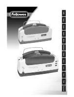
Page 3: ...WITH COMB OPENER O D 4000 PUNCH WITH WIRE CLOSER L OD 4000 PUNCH WITH WIRE CLOSER AND COIL INSERTER OD 3500 W BINDING MODULES OD 3500 COMBO BINDING STATION WITH COMB OPENER AND COIL INSERTER OD 3500 COMBO BINDING STATION WITH W RE CLOSER AND COIL INSERTER ...

Page 4: ...the right side of the Combo Binding Station or OD 4000 Punch using two wing nuts for easy installation Wire C oser The wire closer is capable of binding books up to 1 1 8 28 6mm thick It uses wire sizes from 3 16 to 1 1 4 It has an adjustable closing bar for the different size wires Each end can be adjusted independently to obtain a perfect close The unit attaches to the rear of the Combo Binding ...

Page 5: ...e mandrel 12 c Installing the mandrel on the machine 12 d Adjusting the Mandrel bracket 12 e Adjusting the paper stop 13 f Adjusting the front table lexan guide 13 g Forward off reverse switch 14 h Inserting a coil 14 i Drive wheel stop screw 15 j Cutting a coil 15 10 Attaching Wire Closer module Setup Instructions 18 a Determine the correctwire size b Inserting the wire into the book c Setting th...

Page 6: ...c OD 4000 Electrical schematic Coil Inserter Module Die list 4 5 7 11 13 13 14 15 16 18 20 20 21 21 22 25 8 16 8 17 9 10 1 important Safety Notice Make sure you read this section very carefully Learn to recognize this Safety Alert Symbol The OD 4000 has been designed to provide a very high level of protection to an operator Follow the guidelines below while installing operating and maintaining you...

Page 7: ...ame receptacle if this option is to be used 4 Die installation Diagram 1 Make sure the machine is turned off beforeinstalling die Install the die 1 by sliding it into the opening of the machine located on the left hand side of the machine Make sure the punch pin retainer 2 slides into the slot of the pusher bar Using the two fluted knobs 3 provided with the machine install each handle into the hol...

Page 8: ...an run onto the paper being punched After oiling always punch scrap paper to remove excess oil 5 Setting the paper guides Diagram 2 The paper guide 1 is located on the top hinged cover By loosening the knob 2 counterclockwise the guide can be adjusted to the left or the right so the holes can be centered within the paper being punched For 11 sheets the right hand portion of the guide can be set at...

Page 9: ...ched pile making sure the sheets remain in exact order 2 Removing paper waste Diagram 3 The paper waste is removed by pulling towards you the paper waste drawer 3 It is located directly below the die This should be checked frequently while punching not to allow it to fill up and spill into the machine 3 Paper Jam Reverse knob Diagram 3 Unplug and turn the power oft to the machine before proceeding...

Page 10: ...Diagram 3 ...

Page 11: ...off 1 Check power switch 2 Machine not plugged in 2 Check both ends of power Foot pedal not plugged into machine Top Cover Switch Blown fuse Pin retainer interference Punch stopped in mid cycle Pins not flush with pin retainer cord 3 Make sure foot pedal cable is attached to machine 4 Close top cover 5 Check Fuse 1 5A slot in pusher bar see 2 Check fuses and restart Make sure that all the pins are...

Page 12: ...he most common dies manufactured by Performance Design Special dies are available m Askyourdealerfor 2 T o 1 R o u n d more information Drawings are to 3333 0 172 scale I I I 3 To 1 Round 250 0 172 I I I To 7 R o u n d _ 5 To 1 Roun d 5mm ...

Page 13: ... t 6mm 6MM Round 4 250 3 Hole X 5 16 Drawings are to ...

Page 14: ...Drawings are to scale 5 0 0 250 Sq 2 To 1 S q u a r e 7 t 3333 i 156 Sq 3 To I S q u a r e ...

Page 15: ...r stop bracket 2 to the right side of the OD 4000 using the two black thumb knobs 3 provided Attach the paper stop 4 to the paper stop bracket by sliding the square nut into the slot of the paper stop bracket This can be positioned and tightened by the knob 5 at a latter time when setting the guides to the paper Use two black thumb knobs 6 to attach the book table lexan coil guide to the OD 4000 T...

Page 16: ...7 8 1 24mm 27mm 1 1 1 8 to 1 1 4 28mm 30mm Installing the mandrel on the machine Place the mandrel 1 into the mandrel holder bracket 2 making sure the beveled edge of the mandrel is facing the right side of the machine Both guide pins located on the mandrel need to line up with both slots on the mandrel bracket Use the black knob 3 to tighten the mandrel in place Adjust the height of the mandrel s...

Page 17: ...djusting the front table lexan guide The front table lexan guide 7 7a L 7b has two purposes FIRST When the lexan is in the closed position rotated on top of the coil 7a it will assist the coil to insert smoothly into the book You should use the lexan guide with all books regardless of thickness SECOND With the lexan guide plastic in the open position rotated away from the machine it acts as a supp...

Page 18: ...ng the open end of the coil onto the beveled end of the mandrel Turn the coil so it threads onto the mandrel post 9 and is in front of the drive wheel by one coil Make sure the forward reverse switch is in the forward position Pull the handle 10 down to start the motor and engage the drive wheel 11 to the coil Rotate the coil so it comes close to the edge of the book but not past the book With you...

Page 19: ... if necessary If the mandrel bracket is adjusted after the stop screw has been adjusted it will be necessary to readjust the stop screw Cutting the coil There are special cutter crimper pliers ordered separately that are used to terminate the ends of the coil After the coil is cut the sharp end of the coil will tuck itself under the inside of the coil opening To use the cutter make sure the red do...

Page 20: ...Place switch in either There is a thermal overload in center position Forward or Reverse built inside of the motor Wait 2 Machine not plugged in posibon several minutes below 3 Blown Fuse 2 checking the fuse Check both ends of power cord 3 Check Fuse 1 5amp Coil tightens on the mandrel 1 Mandrel is too small for when inserting I Select proper size coil mandrel see page 12 Coil stops before it is c...

Page 21: ...ly after the motor cools This product has earned the UL Listing Mark and the UL Listing Mark for Canada El 79574 The Cl 3000 has been tested with a duty cycle of 4 seconds on 15 seconds off with a rest period of 2 minutes after 30 seconds of run time The Cl 3000 is also known as the Coil Inserter Module 4300 1 ...

Page 22: ...odule Use the allen key provided with the closing module to secure the handle in place Optional wire holder The wire holder 4 will hold a wire so the book can be placed onto the narrow loops of the wire It is mounted to the chip drawer located on the front side of the OD 4000 The chip drawer should be removed for this procedure There are two round spacers 5 that go behind the wire holder Mount the...

Page 23: ...e two methods for inserting the wire into the book First prep the book by removing the back cover and place it on top of the front cover This will position the binding edge of the wire at the inside cover at the back of the book The traditional way to insert the wire is to place the book on the edge of a table so the holes overhang the table a slight amount Make sure the covers are facing down whe...

Page 24: ...ble on each end allowing the operator to achieve a perfect close at each end of the book Pull the handle on the closer all the way down and adjust both knobs 3 so the top edge 4 of the closing bar lines up with the line 5 next to the wire size you want to close Diagram 7b ...

Page 25: ...the book against the back plate Hold the book with your left hand as you pull the handle 8 down with your right hand Inspect the close and readjust the wire if necessary When the wire is closed properly the narrow loop overlaps the wide loop by about 1 1 6 along the entire length of the book An indication that the wire is not closed tight enough is when the covers or sheets fall out of the book Di...

Page 26: ...the narrow section of the comb opener is facing the front of the OD 4000 punch Attach the comb opener with four black knobs 1 providedwith the comb opener module Use two knobs on each side to secure the unit in position Anach the comb opener handle 2 to the left side of the comb opener using the washer screw provided with the comb opener module Use the allen key provided with the comb opener modul...

Page 27: ...0 7 8 22 2 3 4 19 190 1 25 4 7 8 22 2 220 1 1 8 28 6 1 25 4 250 1 1 4 31 8 1 3 32 27 8 275 1 1 2 38 1 1 3 16 30 1 300 1 3 4 44 5 1 7 16 36 5 360 2 50 8 1 11 16 42 8 425 b Placing the comb onto the rake Place the comb onto the rake with the fingers of the comb facing the front of the machine The solid section of the comb will be facing the rear of the machine Make sure the points of the fingers are...

Page 28: ...ess is now complete e Margin setting The margin on a standard comb die is fixed at 3 32 This margin will work fine until you bind books up to about 1 in comb size After that there is too little paper between the edge of the hole and the edge of the sheet Tearing of a sheet out of the book can occur when handling the book to rough It is recommended when binding books beyond this size you use the op...

Page 29: ...t side of the OD 4000 punch Install the versa switch plug into the same receptacle that the foot pedal plug was removed from Remove the paper stop from the front cover of the OD 4000 The Versa switch comes fully assembled The knob 1 will have to be removed from the assembly Also the two wires 2 attached to the switch will have to be removed Place the switch bracket 3 inside the cover 4 and the pap...

Page 30: ......
Reviews: