ResMed VPAP III ST-A, Service Manual
The ResMed VPAP III ST-A Service Manual is available for free download on our website. This comprehensive manual provides users with valuable instructions and detailed information on operating and maintaining the VPAP III ST-A device. Obtain this essential resource effortlessly from our website manualshive.com.
Share
Download


Reviews:
No comments
Related manuals for VPAP III ST-A
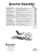
Kinetec Spectra Essential
Brand: Patterson Medical Pages: 104

5001 024 ML
Brand: Dowell Pages: 4

Tri-Tronics PRO70
Brand: Garmin Pages: 16

AVIJECTOR
Brand: Kaycee Pages: 12
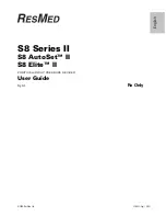
S8 AutoSet II
Brand: ResMed Pages: 20

TMJ
Brand: ThermoTex Pages: 2

Hallux Valgus Combo ComforT 510
Brand: Otto Bock Pages: 52

NE2007
Brand: Laica Pages: 8

Také One-Touch
Brand: Richell Pages: 4

Wireless Edition Newa+
Brand: Newa Pages: 3

OPTIFLOSS ND-DC01
Brand: Silk'n Pages: 217

myself
Brand: JCS Wellness Solutions Pages: 12

Tropical Series
Brand: PC MARKETING Pages: 20

Wall Mounted Lighted Up Mirror
Brand: PB TEEN Pages: 2

D02-021
Brand: PawHut Pages: 7

Buddy Pack
Brand: ActIjoy Pages: 18

WINNCARE PEDIA SPORT
Brand: Askle Sante Pages: 24

Coala
Brand: Coala Life Pages: 6


