EN
INSTRUCTION
ED-T70W
IN20051 REV. B, 2021-11-26
C
Caauuttiioonn!! Read and understand the instruction before using the product.
C
Caauuttiioonn!! Ensure that the installation complies with local safety
regulations.
C
Caauuttiioonn!! Before installation or maintenance, the power supply should first
be disconnected. Installation or maintenance of this unit should only be
carried out by qualified personnel. The manufacturer is not responsible
for any eventual damage or injury caused by inadequate skills during instal-
lation, or through removal of or deactivation of any security devices.
Function
ED-T70W is a touch display that is easy to use. It is connected to a
controller and connects to the controller's web interface. The web
interface is used to control and monitor the controller and application.
Technical Data
Supply voltage
12…48 V DC or 24 V AC (20…36 V AC, 50…60 Hz) or
PoE IEEE 802.3af (Power over ethernet)
Power
consumption
5 VA
Protection class
IP20
Storage
temperature
-20…70 °C
Ambient
temperature
0…45 °C
Ambient humidity
5…85 % RH non-condensing
Dimensions, exter-
nal (WxHxD)
177,1 x 110,1 x 14, 8 mm
Display type
Projected capacitive multi- touch
Touch panel
7" TFT IPS
Resolution
1024 x 600 px
Weight
298 g
Installation
C
Caauuttiioonn!! The display should not be mounted in direct sunlight, in a humid
or dusty environment or in an area with fast temperature variations.
Connect the display to the controller with the ethernet cable.
The display has a flush mounting plate attached at delivery. There is also
a front mounting frame included.
Flush mounting
1. Remove the back plate for flush mounting from the display:
a. Loosen the screws that secure the flush mounting plate on the
bottom edge of the display.
b. Rotate the back plate upwards, the top edge is the axis of
rotation.
2. Install the back plate in the flush mounting box in the wall. The
contact for the display should be in the upper half of the plate.
3. Mount the display on the plate by rotating the display downwards
onto the plate and secure it with the screws (reverse the procedure
in step 1).
Front mounting
1. Make a rectangular hole in the front of the control cabinet. The
cutout size is 137 mm x 89 ± 1 mm. There is a template for the cut
out available on Regin 's homepage www.regincontrols.com.
2. Insert the unit into the hole.
3. Assemble the mounting frame to display by snapping it to the
assembly holes on the sides of the display.
4. Secure the display with the screws in the mounting frame.
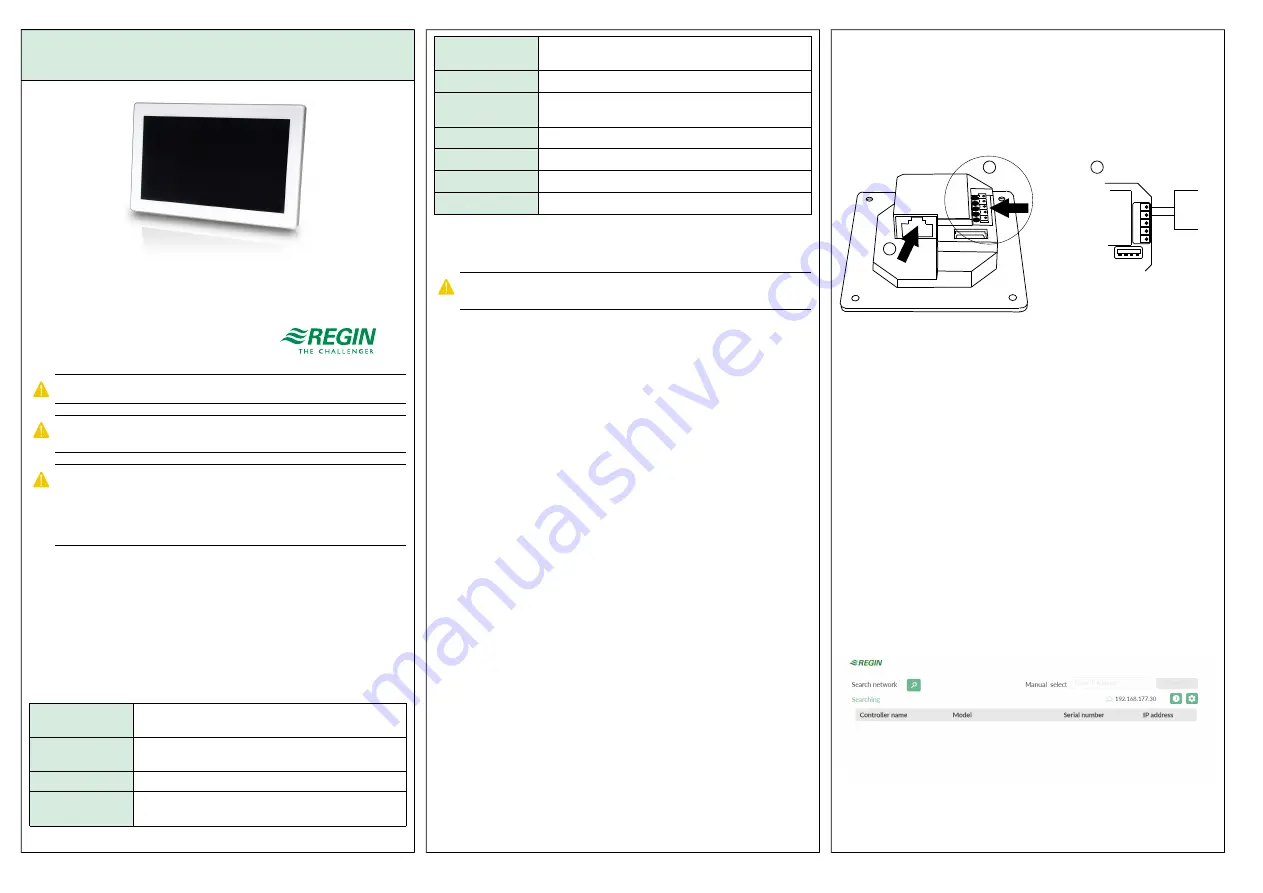
Wiring
Power connection
The display con be connected to power in two different ways.
1. With the ethernet cable (PoE, Power over ethernet).
2. By using an external power supply, Such as Regin's X1111.
12 V- 48V DC
12-24V AC
PoE
GND
V+
GND
RS485A
RS485B
1
2
2
max. 5W
IP20
GND
V+
24 V DC
+
-
Figure 1 Wiring. 1: Ethernet cable 2: External power supply
Connection to the controller
The display is connected to the controller with the ethernet cable.
Settings
The display starts when it's connected to power.
When the display is started the start screen is shown, see
below. The start screen is also shown when the previously
connected controller is not available in the network.
The start screen is always available by sweeping from top to bottom on
the display.
The start screen gives information about the connection and the
available controllers in the network. On the start screen there are
buttons for searching the network, more information about the display,
and for communication settings. See the
section for more
information.
Figure 2 Start screen
ED-T70W
1