


Installer
: Please complete the details on the back cover and leave this
manual with the homeowner.
Homeowner:
Please keep these instructions for future reference.
Certified to/Certifié pour: CSA 2.17-2017
ANSI Z21.88-2017
CSA 2.33-2017
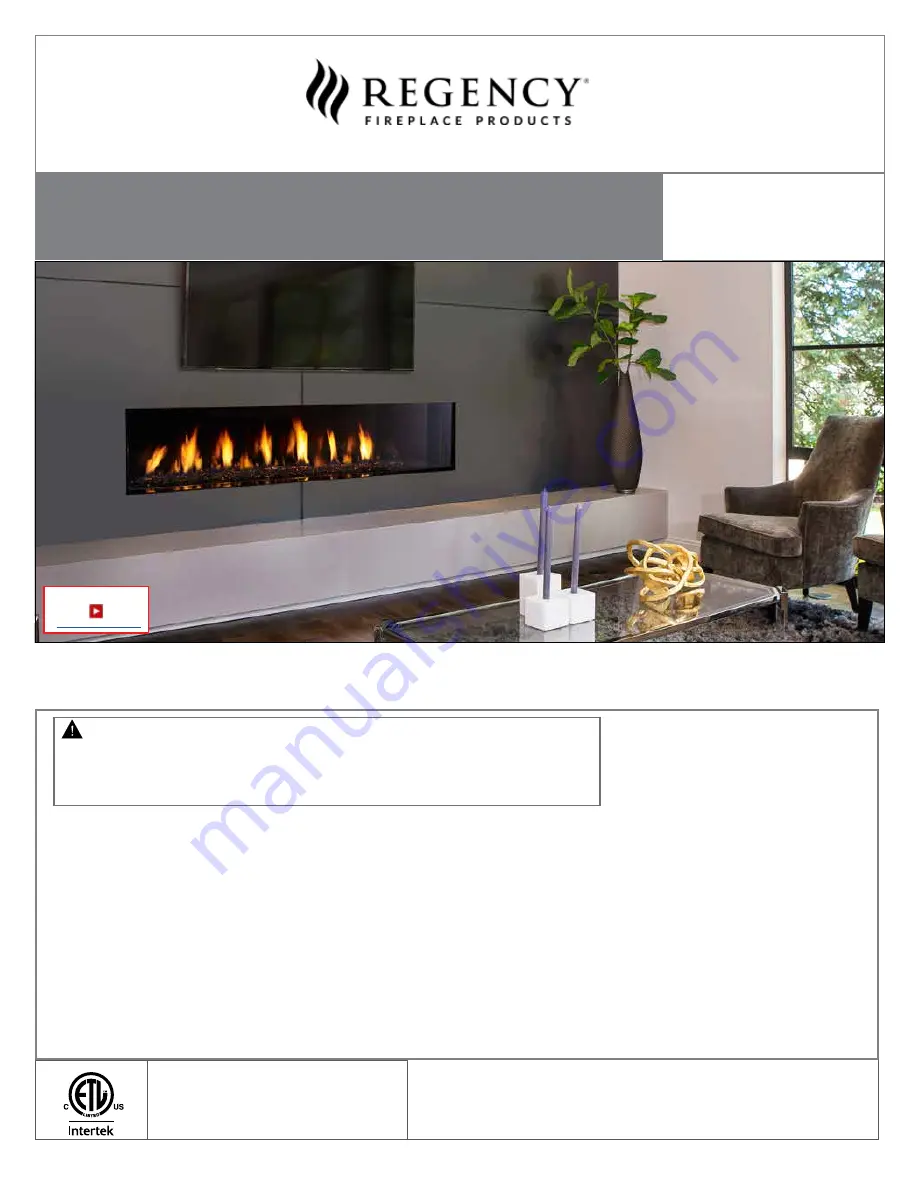
City Series®
CV72E POWER VENT
Owners &
Installation Manual
STYLE
MODEL
Single sided CV72EPV-NG / CV72EPV-LP
Tested by:
www.regency-fire.com
- Do not store or use gasoline or other flammable vapors and liquids in the vicinity of this or any other
appliance.
- WHAT TO DO IF YOU SMELL GAS
•
Do not try to light any appliance.
• Do not touch any electrical switch: do not use any phone in your building.
Leave the building immediately.
• Immediately call your gas supplier from a neighbour's phone. Follow the gas supplier's
instructions.
• If you cannot reach your gas supplier, call the fire department.
- Installation and service must be performed by a qualified installer, service agency or the gas supplier.
Warning
Fire or explosion Hazard
failure to follow safety warnings exactly could result in serious
injury, death, or property damage.
919-856l
FPI FIREPLACE PRODUCTS INTERNATIONAL LTD. 6988 Venture St., Delta, BC Canada, V4G 1H4
03.08.22
New York 72
http://bit.ly/2yIGUao
Summary of Contents for City CV72E Series
Page 113: ...City Series CV72EPV 113 notes ...
Page 118: ...118 City Series CV72EPV warranty ...
Page 119: ......


