background image

Summary of Contents for TM 5-4000

Page 1: ...REFERENCE USE ONLY MOT TO BE TAKEN FROM LIBRARY K9 st i iii g ...

Page 2: ...art Catalog Pneu matic Chain Saw Model Timberhog 24 published by the Reed Prentice Corp is furnished for the information and guid ance of all concerned AG 062 11 4 26 41 PC C June 10 1941 G C Chief of Staff Official J A ULIO Majdr General The Adjutant General ...

Page 3: ...94 23006 Incl P O 57294 Contract W978 eng 5092 Serial Nos 23705 23804 Incl P O 57737 Contract W978 eng 5376 Serial Nos 24082 25051 Incl Title Pneumatic Chain Saw Model Timberhog THA 24 Contractor Reed Prentice Corporation Worcester Mass Major Components a Motor THA 52 b Tailstock THS 372 c Guide Bar THS 197 d Chain 15 THE 24 ...

Page 4: ... MANUAL 9 to 19 Incl Air Motor Servicing 9 Assembly and Disassembly 11 Gear Box 13 Sprocket Shaft 13 Air Motor Parts Fig 6 10 Motor and Gear Box Fig 7 12 Tailstock Parts Fig 8 14 Tailstock 15 Tailstock Fig 9 16 Chain Fig 10 17 Chain Sharpening 18 Resetting 18 Jointing 18 Replacing Damaged Teeth 19 PARTS LIST 21 to 27 Incl Motor Parts Figs 12 and 13 21 and 22 Motor Parts List 21 and 23 Tailstock Pa...

Page 5: ...sure lubrication of chain Three way oiling valve Adjust petcock for rate of flow GreasS Governor OH rotor LCACln 1 Remove plug underneath add R J ve plug f ll with S A E 10 motor oil light body grease about 1 table rePlenlsh after every 8 hrs Pera n spoonful every 2 or 3 months CAUTION Be sure breather is closed when using air pressure Open breather when using gravity feed LUBRICATING DIAGRAM FIG ...

Page 6: ...orated in the left handle which directly controls the amount of air sup plied to the rotor A 30 length of hose isolates the coupling joint from the operator Should the coupling separate the wild hose end is far enough away from the operator to prevent injury Oiling Before starting to operate the saw a careful check should be made to see that proper quantities of oil and grease are available at the...

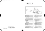
Page 7: ...Throttle Chain Tension Adjusting Handle Hose FIG 2 OPERATING GUIDE ...

Page 8: ...through the log a curving cut causes binding If the cut curves examine the cutter bar for uneven wear Both sides of the groove should be evenly worn Minor discrepancies can be dressed out with a file When felling a notch is cut on one side of the tree in the direction of the fall The final cut is then made from the opposite side It is important to maintain a constant flow of oil to the chain Lack ...

Page 9: ...NTER RAKER I L H CUTTER I L H RAKER I RHCUTTER I RH RAKER I LH CUTTER 3 CONN LINKS CENTER RIGHT RIGHT RAKER CUTTER RAKER ONE COMPLETE CUTTING ACTION LEFT LEFT CUTTER RAKER STARTING WITH RIGHT RIGHT CUTTER CUT 1ST SECTION CENTER LEFT LEFT FjAKER CUTTER RAKER ONE COMPETE CUTTING ACTION RIGHT RIGHT CUTTER RAKER STARTING WITH LEFT LEFT CUTTER CUT C ND SECTION IkJIDl lDTAMT TO SHARPEN CHAIN GRIND OR FI...

Page 10: ...combination of cutters and rakers form a zigzag pattern Figure 4 shows that every set of six links forms a cutting action or sequence which is repeated throughout the chain SHARPENING the saw chain is a simple operation and can easily be performed by the operator It consists merely of filing the front cutting edge of each tooth taking care that the original angle is not changed This can be perform...

Page 11: ...REED PRENTICE TIMBERHOG AIR SAW SPROCKET SHAFT 333 500 666 833 1000 1166 1333 1500 RPM TORQUE 8 tP_ CURVE WITH 90 AIR TESTED WITH 20 FT Jfe HOSE REED PRENTICE CORR WORCESTER MASS THA 77 FIG 5 ...

Page 12: ...INSTRUCTION BOOK MAINTENANCE MANUAL for Reed Prentice Portable Timberhog Saw ...

Page 13: ...a slight radius to improve the cutting action of the chain The tailstock contains the idler which is adjustable and is used to remove the slack in the chain and to govern the tension There is a spring device incorporated in the tailstock which acts as a shock absorber An oil tank mounted on top of the tailstock supplies oil to lubricate the chain and cutter bar Air Motor The motor contains a built...

Page 14: ...ET3 COMPLETE I ASSEMBLY 32 49 Uo EIC I COMPLETE JL ASSEMBLY 051 H 52 53 36 0 37 TWO 41 33 35 36 6 av O 62 o rwo 63 f 64 65 EID FIG 6 AIR MOTOR PARTS 10 ...

Page 15: ...inion spacer E5 Fig 7 after which the rotor can be pulled out of the motor When assembling a rotor always pull up tightly on the lock nut E8 Fig 7 which holds the pinion in place This will pull the rotor up against the end plate to a point where it may actually rub a little In pulling up tightly on the governor body 57 when assembling the other end of the motor however the rotor will be pulled tow...

Page 16: ...FIG 7 MOTOR AND GEAR BOX 12 ...

Page 17: ...arts E13 E12 and Ell are then assembled in the order named The bearing E10 is assembled into the end cap E9 It will be necessary to heat this end cap before assembling the bearing The bearing El7 is assembled into the steel bearing housing E18 This bearing is of the single seal type and the sealed end should be toward the sprocket The bear ing and support E18 are placed into the main housing E23 T...

Page 18: ...HIS H43 HIS HI9 HI7 H24 o o Hi H2 H9 oHI I H6 H8 H 10 H7 j H27 H28 H29 H4i H26 H25 H30 H3I HI4 H35 H32 FIG 8 TAILSTOCK PARTS See Fig 9 ...

Page 19: ...ion of the idler which puts more or less tension upon the chain as required The tailstock also contains the oil reservoir which supplies oil to the cutter bar and the chain A small air pump HIS is used to set up a pressure in the tank and force the oil into the cutter bar during the cutting action The oil is fed from the reservoir to the cutter bar through the oil line and fittings H17 HIS and H19...

Page 20: ...FIG 9 TAILSTOCK ...

Page 21: ... H CUTTER I LH RAKER I RH CUTTER 3 CONN LINKS I L H CUTTER I L H RAKER 1 R H CUTTER I RH RAKER 1 L H CUTTER 3 CONN LINKS CENTER LEFT LEFT RIGHT RIGHT RARER CUTTER RAKER CUTTER RAKER CUTTER ONE COMPLETE CUTTING ACTION STARTING WITH RIGHT CUT 1ST SECTION RAKER CUTTER RAKER CUTTER RAKER CUTTER ONE COMPLETE CUTTING ACTION STARTING WITH LEFT CUT gNDSECTlON IMPORTANT TO SHARPEN CHAIN GRIND OR FILE CENTE...

Page 22: ...s are riveted The shoulder properly spaces the side cutters so that clearance is maintained with the center links or rakers to provide a flexible chain It is generally not necessary to do more than file the front edges of the teeth to keep the saw cutting efficiently However occasionally other maintenance is required Sharpening the Saw Chain To sharpen the saw chain it is filed or ground on the fr...

Page 23: ...at gage is provided which can be used to gage the clearance properly Replacing Damaged Teeth To remove a damaged cutter it is necessary to grind or file the heads from the two rivets that hold the plain link paired with the cutter Do not attempt to remove one rivet at a time because these are made with a shoulder and will not pass through the cutter A cold chisel can be used to separate the plain ...

Page 24: ...PARTS UST for Reed Prentice Timberhog Saw IMPORTAIVT SUPPLY SERIAL NUMBER OF MACHINE WHEN ORDERING REPAIR PARTS ...

Page 25: ... Rd End Key Sprocket Shaft TV XA XJ4 Rd End Key Fafnir Ball Bearing Motor Housing Cap 7 Tooth Sprocket y 2 Plain Washer 20 SAE Check Nut Motor Housing Chain Guide Clamp y 2 M I Street Elbow 5 _24X104 Hex SAE Bolts Y Lockwashers 24 SAE Hex Nuts 1 Hose section consisting of Yn leader 30 long with manufac turer s standard coupling at motor able universal hose coupling to J4 21 H J CJ PART NO THA 60 T...

Page 26: ...wmi E3 COMPLETE ASSEMBLY 38 e o 37 TWO o 41 32 w 49 TWO EIC COMPLETEN IASSEMBLY 53 52 61 O 62 m O TWO I63 f 64 33 34 35 36 65 56 six f 44 TWO 55 A 58 TWO 59 TWO EID FIG 13 22 ...

Page 27: ...e Governor Valve Button Liner End Plate Dowel Liner Rotor Rotor Blades Governor Body Governor Weight Pin Governor Weight Governor Push Pin 10 32 XS s Fil Hd Screw 10 32 Lockwasher f l C 76505 I Governor Governor Lever Pin Governor Lever Button I Governor Lever Needle Valve Packing Needle Valve Packing Cup Needle Valve Needle Valve Cap Motor Housing Cover Mi Alien Pipe Plug Yt Alien Pipe Plug Motor...

Page 28: ...O i i fe ...

Page 29: ...25 3 Way Oiling Stem H 26 3 Way Oiling Stem Alien Pipe Plug H 27 Detent for Stem Y 4 Xy 4 Alien Headless Set Screw H 28 Detent for Stem Spring H 29 Detent for Stem Ball H 30 3 Way Oiling Stem Oil Stem Collar H 31 3 Way Oiling Stem Taper Pin H 32 Door Catch H 33 Door Catch Washer H 34 54 20 Wing Nut H 35 Door Catch Stud H 41 Cork Gasket 3 Way Oiling Stem H 42 Cotter Pins H 43 Air Pump Nipple Weathe...

Page 30: ......

Page 31: ...Raker THS 420 18 S 10 Rivet THS 321 104 S 11 Raker Gage THG 333 1 S 12 6 xy s Dia at Point Punch 1 S 13 H Cold Chisel 1 S 14 Rivet Anvil THG 214 1 S 15 5 Combination Pliers with two position slip joint 1 S 16 Setting Tool 1 S 17 8 oz Ball Peen Hammer 1 S 18 8 Adjustable Wrench 1 S 19 ft Xl 4 Open End Wrenches 1 S 20 H Xft Open End Wrenches 1 S 21 8 Insulated Screw Driver 1 S 22 Alien Socket Wrench...

Reviews: