background image

Original  Instruction  Manual

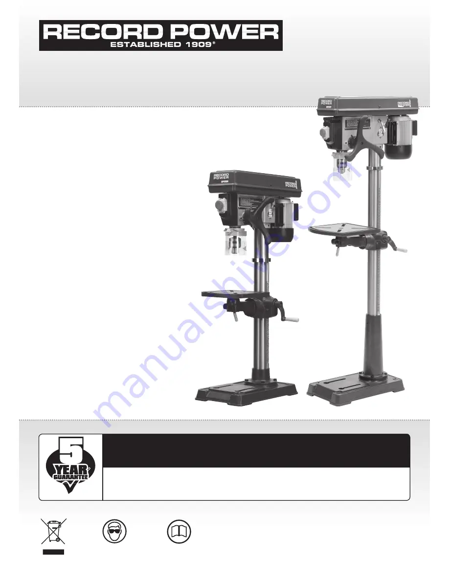
DP58P

 Heavy Duty 

Pedestal Drill with 50” 
Column & 5/8” Chuck

DP58B

 Heavy Duty 

Bench Drill with 30” 
Column & 5/8” Chuck

Important

For your safety read instructions carefully before 
assembling or using this product.
Save this manual for future reference.

Always wear safety glasses when 
using woodworking equipment.

Always read the instructions 
provided before using 
woodworking equipment.

i

Kg

Version 3.1

April 2014

To register this product please visit

www.recordpower.info

It is important to register your product as soon as possible in order to receive efficient after sales 

support and be entitled to the full 

5 year guarantee

. Your statutory rights are not affected. 

Please see back cover for contact details.

Summary of Contents for DP58P

Page 1: ...ference Always wear safety glasses when using woodworking equipment Always read the instructions provided before using woodworking equipment i Kg Version 3 1 April 2014 To register this product please visit www recordpower info It is important to register your product as soon as possible in order to receive efficient after sales support and be entitled to the full 5 year guarantee Your statutory r...

Page 2: ...hich can result in severe eye damage Protective eyewear or other suitable eye protection or face shield should be used at all times Everyday spectacles only have impact resistant lenses They are not protective eyewear and do not give additional lateral protection Use respiratory protective equipment dust mask etc if the machining operation creates dust Exposure to high levels of dust created by ma...

Page 3: ...ools that are not in use Ensure that the floor area is kept clean and clear of any dust and debris that may create trip or slip hazards 11 Consider the work area environment Do not expose the machine to rain or damp conditions Keep the work area well lit and ensure that there is artificial lighting available when there is insufficient natural light to effectively light the work area Lighting shoul...

Page 4: ... from being used without the guards in place Never attempt to bypass or modify the interlocks to allow the machine to be used without the guards in place 27 Maintain your machine with care This manual gives clear instructions on installation set up and operation of the machine and also details any routine and preventative maintenance that should be performed periodically by the user Remember alway...

Page 5: ... been purchased from a retailer the 5 year guarantee is transferable and begins on the date of the first purchase of the Product and in the event of a claim under this guarantee proof of the original purchase date will be required to validate the warranty period 2 Claims Procedure 2 1 In the first instance please contact the Authorised Dealer who supplied the Product to you In our experience many ...

Page 6: ...83dB A Sound Pressure Level 83dB A A Head B Column table support and rack DP58P C Column table support and rack DP58B D Table E Chuck F Chuck key G Feed handle H Base I Chuck guard J Drift key K Table support locking handle L Table crank handle M M10 hex head bolts x 4 N M5 Hex head socket bolt O M5 hex wrench P M4 hex wrench Q M3 hex wrench R M2 hex wrench A C B D H E F Separate all parts from pa...

Page 7: ...n Lock handle Belt tension cam handle Feed handle Column collar Table support Table crank handle Rack Base Column support Column Table Depth scale Depth scale indicator Depth scale lock On off switch Feed spring Table support locking handle DP58P shown Table locking lever Chuck Chuck guard ...

Page 8: ...a tapped hole Ensure that the locking handle is passed through the plain bore and into the tapped hole in order for the table support to clamp correctly around the column Fig 7 2 Fit the table crank handle to the shaft protruding from the table support and secure using the M6 x 8 mm blind set screw Fig 7 3 Attach the table to the table support by placing the column on the underside of the table th...

Page 9: ...nd set screws do not protrude into the inside of the head assembly Before fully tightening the screws check that the head is correctly aligned with the base so that the spindle is above the centre line of the base casting To attach the feed handle to the head assembly align the roll pin on the inside of the handle collar Fig 7 6 with the slot in the rise and fall pinion shaft Fig 7 7 and secure in...

Page 10: ...eign bodies that may prevent the chuck from seating correctly Clean both surfaces with white spirit to remove any heavy deposits of grease and dirt and then apply a thin coat of silicon spray or similar to both tapers before assembling Once the chuck is in position tap it firmly and squarely with a soft faced mallet to ensure it is fully seated on to the spindle Fig 7 9 To fit the chuck guard plac...

Page 11: ...ig 8 3 Fig 8 5 Angle scale Fig 8 4 Locking bolt Using the Base as a Work Table If the size of the work piece is too large to be accommodated using the work table it can be swung away from the chuck so that the base can be used to support the work piece Fig 8 2 To do this unscrew the table support locking handle and rotate the table around the column of the machine It may be necessary to loosen the...

Page 12: ... the event of a power failure first locate and rectify the source of the failure If the fault is within the power circuit of the workshop there may be an underlying cause circuit overload etc that should be investigated by a qualified electrician before attempting to restore the power source Once the power is restored the machine can be re started by pressing the green button marked I on the switc...

Page 13: ...uard Fig 9 1 2 Unscrew the belt tension locking handles Fig 9 1 located at each side of the head unit 3 Use the belt tension cam handle to release tension on the drive belt by turning it anti clockwise 4 Re position the drive belts Fig 9 2 to correspond with the appropriate speed as shown on the speed chart inside the belt guard Fig 9 3 5 Reapply tension to the drive belt by turning the belt tensi...

Page 14: ... possible damage place one hand under the chuck to catch it when it becomes disengaged along with the arbor Aligning the Table with the Chuck To ensure the table is at 90º to the chuck from side to side make sure the angle scale is set to 0º Fig 9 6 To ensure the table is at 90º to the chuck from front to back place a drill bit in the chuck and check the angle with an engineer s square from the si...

Page 15: ...ut and take the cap and spring from the threaded spindle Take the new cap and spring and place onto the threaded spindle Fig 9 10 ensuring the central straight piece of the spring is inserted into the slot on the threaded spindle Fig 9 11 With the headstock spindle in its lowest position carefully rotate the cap anti clockwise to apply tension to the spring When enough tension has been applied to ...

Page 16: ... the circuit In the case of the BS1363 plug for use in the UK always ensure that it is fitted with a fuse conforming to BS1362 appropriate to the rating of the machine If replacing the original fuse always fit a fuse of equivalent rating to the original Never fit a fuse of a higher rating than the original Never modify the fuse or fuse holder to accept fuses of a different type or size Where the c...

Page 17: ... motors can be used simultaneously giving maximum suction but in this mode the extractor must be switched off for 20 minutes every hour 0 5 micron filtration DX5000 High Filtration Dust Extractor Bag type extractor 200 litre capacity Twin 1 kW motor suitable for heavy usage ie if one motor is switched off for 20 minutes then the other can be used thus enabling continuous usage Or both motors can b...

Page 18: ...rilling 1 Not supported or clamped properly 1 Use drill press vice to support and clamp work Drill bit binds in workpiece 1 Workpiece pinching drill bit or excessive feed pressure 1 Support workpiece or clamp it 2 Improper belt tension 2 Adjust belt tension Excessive drill bit run out or wobble 1 Bent drill bit 1 Replace drill bit 2 Worn spindle bearings 2 Replace bearings 3 Drill not properly ins...

Page 19: ...pindle 2 12 Bearing ball 13 Parts Lists Diagrams 1 1 Screw hex soc set 1 2 Collar rack 1 3 Gear rack 1 4 Crank 1 6 Table 1 7 Clamp table 1 8 Screw hex HD M16 x 20 35 1 9 Table assembly w scale 1 10 Base 1 11 Support column 1 12 Screw hex HD M10 x 1 5 40 1 13 Screw hex soc set M10 x 1 5 12 1 14 Tube column 1 15 Rack 1 16 Clamp column 1 17 Support table w indicator 1 18 Worm elevation 1 19 Pin gear ...

Page 20: ...nsert spindle 3 8 Guard pulley w labels 3 9 Screw RD HD Washer M6x1 0 16 3 10 Screw set M10x1 5 12 3 11 Motor pulley 3 12 Knob 3 13 Screw pan HD M5 x 0 8 12 3 14 Pivot idler 3 15 Pulley centre 3 16 Bearing ball 15mm 3 17 Belt V M26 3 18 Foam washer 3 19 Lock washer Ext M6 Spare Parts List for Diagram 3 13 Parts Lists Diagrams Cont ...

Page 21: ... 4 17 NVR switch 4 18 Switch key 4 19 Switch plate Cover 4 20 Lead assembly 3 4 21 Special screw set 10 x 1 5 27 4 22 Nut hex M10 x 1 5 4 23 Seat spring 4 24 Retainer spring 4 25 Spring torsion 4 26 Spring cap 4 27 Hex nut M12 x 1 5 8 4 28 Head w pointer and trim 4 32 Tie wire 4 33 Power cable w plug 4 35 Pan HD M6 x 1 0 12 screw 4 36 Cable clamp 4 37 Motor bracket support 4 38 Hex HD M8 x 1 25 20...

Page 22: ...ives MACHINERY DIRECTIVE 2006 42 EC repealing replacing Directives LOW VOLTAGE DIRECTIVE 2006 95 EC ELECTROMAGNETIC COMPATIBILITY DIRECTIVE 2004 108 EC EN 55014 1 2006 EN 61000 3 2 2006 EN 61000 3 3 1995 A1 A2 EN 55014 2 1997 A1 and conforms to the machinery example for which the EC Type Examination Certificate No AM50167614 AN50167613 AE50136034 at Am Grauen Stein D 51105 Cologne Germany and comp...

Page 23: ...23 ...

Page 24: ......

Page 25: ...cordpower co uk Eire Record Power Ltd Centenary House 11 Midland Way Barlborough Links Chesterfield Derbyshire S43 4XA Tel 01246 571 020 Fax 01246 571 030 www recordpower co uk Australia Tools 4 Industry Po Box 3844 Parramatta 2124 Tel 1300 124 422 Fax 1800 262 725 www recordpower com au New Zealand Tools 4 Industry Po Box 276079 Manukau City 2241 Tel 0800 142 326 Fax 09 2717 237 www recordpower c...

Reviews: