background image

1

Original  Instruction  Manual
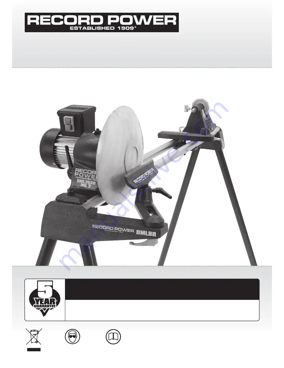
DML36SH-CAM

 Swivel Head 4 Speed Intermediate Lathe

Important

For your safety read instructions carefully before 
assembling or using this product.
Save this manual for future reference.

Always wear safety glasses when 
using woodworking equipment.

Always read the instructions 
provided before using 
woodworking equipment.

i

Kg

Version 2.0

October 2012

To register this product please visit

www.recordpower.info

It is important to register your product as soon as possible in order to receive efficient after sales 

support and be entitled to the full 

5 year guarantee

. Your statutory rights are not affected. 

Please see back cover for contact details.

Summary of Contents for DML36SH-CAM

Page 1: ...sses when using woodworking equipment Always read the instructions provided before using woodworking equipment i Kg Version 2 0 October 2012 To register this product please visit www recordpower info It is important to register your product as soon as possible in order to receive efficient after sales support and be entitled to the full 5 year guarantee Your statutory rights are not affected Pleas...

Page 2: ...er Guarantee 5 Specifications 6 Assembly Instructions 7 Intended Use of the Lathe Basic Woodturning Instructions 8 Control Identification Functions 9 Lathe Operation 10 Maintenance 11 Troubleshooting 12 Spare Parts Identification 13 Electrical Connection Wiring Diagram 14 DML BR Bowl Turning Attachment Assembly EU Declaration of Conformity ...

Page 3: ...er co uk where you can find various woodturning tuition articles and projects Please ensure you have sufficient basic skills before using this machine Basic lathe use and woodturning operations can be found in this manual in section 8 Record Power and the Environment Considerations of environmental issues are an integral part of the design production and other associated aspects of this product an...

Page 4: ...ting to use the machine Indicates an instruction that requires particular attention Wear protective eyewear Use respiratory protective equipment Use suitable protective footwear Use hearing protection Use protective work gloves Indicates a risk of severe personal injury or damage to the machine Indicates a risk of severe personal injury from electrical shock Risk of personal injury from lifting of...

Page 5: ...ll times When using a leg stand or cabinet base that is designed to be fitted to the machine always ensure that it is securely fastened to the machine using the fixings provided If the machine is suitable to be used on a workbench ensure that the workbench is well constructed and capable of withstanding the weight of the machine The machine should always be securely fastened to the workbench with ...

Page 6: ...se extra supports roller support stands etc for any work pieces large enough to tip when not held down to the table top Do not use another person as a substitute for a table extension or as additional support for a work piece that is longer or wider than the basic table or to help feed support or pull the work piece Do not attempt to machine more than one work piece at a time When feeding the work...

Page 7: ... operation For further instructions please see the section of this manual entitled Intended Use of the Lathe Basic Woodturning Instructions Do not attempt to remount a work piece that has been turned on a faceplate unless you are deliberately turning eccentric work You cannot remount faceplate turned work and expect it to run true as the timber will have expanded or contracted Do not remount a wor...

Page 8: ... Product to you In our experience many initial problems with machines that are thought to be due to faulty parts are actually solved by correct setting up or adjustment of the machines A good Authorised Dealer should be able to resolve the majority of these issues much more quickly than processing a claim under the guarantee 2 2 Any damage to the Product resulting in a potential claim under the gu...

Page 9: ... Please take care to follow all instructions when assembling making sure that all critical kinematic areas are correctly positioned so that you enjoy optimum performance i 5 Specifications Maximum distance between centres 36 914 mm Maximum bowl diameter over bed 9 229mm Maximum bowl diameter with DML BR fitted 12 305 mm Maximum spindle diameter 6 152 mm Pulley speeds 450 950 1500 2000 rpm Spindle ...

Page 10: ...den bench mounting washers not required on DML24S Legstand for use when mounting to a wooden bench 7 Toolrest 8 2 x angle straps 9 2 x long bolts threaded bar 10 Long stem locking handle M12 bolt toolrest 11 Tailstock centre 12 Two prong drive centre 13 Pry bar 14 2 x allen keys 15 Spanner 16 2 x bed bars separate box 17 2 x bushes 18 2 x washers 19 2 x nyloc nuts 20 Locking handle 11 12 13 14 10 ...

Page 11: ...ebound from the floor back up the legs and into the bench The legs should be braced at approximately one third of their height from the floor and should be braced both along the length and width of the bench If possible the bench should be bolted to the floor but it should NEVER be fixed to any of the surrounding walls and should ALWAYS be free standing 6 Assembly Instructions cont WARNING Inadequ...

Page 12: ...useful at this point to make sure that the legs are all aligned correctly and adjust if necessary The bottoms of the legs are angled slightly to provide a solid base During assembly it is possible for the legs to become twisted To align the legs slacken off the nut and twist the legs so the angle on the bottom of the leg lies flat on the floor Fig 6 6B Correct alignment of the legs and bed bars is...

Page 13: ...e drilled holes 6 Place the square straps on each end of the assembly ensuring that the kinematic locations oppose each other Fig 6 4A i e the raised area on the angle strap opposes the recess on the end bracket 7 Pass the 12mm threaded bar through the angle strap end bracket and bench Place the washer and nut on to the top of the bar and wind down approximately four threads 8 Do this on both end ...

Page 14: ...to the front of the lathe opposing the raised area on the tailstock Figs 6 8A 6 8B 3 Place the bush onto the tailstock screw Fig 6 9 4 Feed the washer onto the tailstock screw under the bush and tighten the nyloc nut to secure the assembly Fig 6 10 5 Use a spanner to tighten the Nyloc nut on the underside of the tailstock assembly Fig 6 11 Please note Sensitivity of the cam is adjusted with this n...

Page 15: ...nts are used one for the banjo where kinematic points are not used 3 Place the bush onto the tailstock screw Fig 6 13 4 Feed the washer onto the tailstock screw under the bush and tighten the Nyloc nut to secure the assembly Fig 6 14 4 As before use a spanner to tighten the nyloc nut on the underside of the toolrest assembly Fig 6 15 Please note Sensitivity of the cam is adjusted with this nut To ...

Page 16: ... 20 Caution This component is very heavy and will not be stable on the bed bars until the nut and bolt are fastened Assistance should be sought 4 Tighten the locking bar into the nut securing the headstock assembly Fig 6 21 5 Rotate the spindle by hand and inspect the drive belt on the pulleys ensuring that it runs true Fig 6 22 If it doesn t remove the first grub screw these are two grub screws i...

Page 17: ...17 6 Assembly Instructions cont Fig 6 23 ...

Page 18: ... This will reduce the amount of roughing out needed and also maximise the possible diameter of the final piece 1 Using a square or rectangular profile blank draw two lines one from each opposing diagonal corner to the other at each end of the blank The point where the lines intersect indicates the centre of the blank See fig 8 2 If using irregular shaped timber a centre finder is an invaluable too...

Page 19: ...e angle of the cutting bevel of the gouge is too shallow and will cause it dig in to the work piece or snatch the tools from your hands Using the Skew Chisel Skew chisels are available in both flat and oval profiles The curved profile is favoured by many as it gives better results more easily Skew chisels are ideal for creating beads refining the profiles and can be used to create a final smooth f...

Page 20: ... Firmly lock before slide along bed bars and swivel mounting work Toolrest lock Locks toolrest post into base Turn clockwise to lock Toolrest cam lock Locks toolrest base to bed bars Turn clockwise to lock Tailstock cam lock Locks tailstock to bed bars Turn right to lock Position tailstock along bed bars before locking Motor plate clamp Locks motor when belt is tight Loosen to adjust belt for sele...

Page 21: ...se the lowest speed that produces acceptable results Any item that cannot be turned over the bed bars MUST be turned using the lower speed range Most turning can be safely and effectively achieved between 400 and 2000 rpm The additional speeds achievable with this unit are for specialist turning such as high speeds for miniature work pens and lace bobbins and slow speeds for thread cutting for exa...

Page 22: ...over 9 Reconnect the power plug to the power source Turn the lathe on and check the spindle If not turning at the desired speed repeat steps above starting with step 1 WARNING Do not operate the lathe without the headstock cover locked in place Loose items clothing or hands may enter the opening and become entangled in rotating parts Serious injury could occur CHANGING THE HEADSTOCK FITMENT To cha...

Page 23: ...tor Fig 10 1B 2 Release belt tension lever Fig 10 2 3 Supporting the motor with one hand Remove the drive belt from the motor pulley Fig 10 3 Lower the motor and tighten the tension lever 4 Unscrew the Allen bolt and remove this with the washer from the end of the spindle Fig 10 4 5 Remove the top grub screw from the spindle pulley Loosen the bottom dog grub screw a few turns so that the pulley wi...

Page 24: ...laced the new belt on the spindle pulley proceed to step 13 8 Remove the spindle from the headstock and take out the pulley 9 Using a suitable brass rod or piece of timber knock out the back bearing using a mallet Fig 10 8 This back bearing should now be removed 10 Now that the back bearing has been removed pass a piece of timer or brass rod through from the other direction and knock out the front...

Page 25: ...olt should only be turned until finger tight Fig 10 13 then apply a 1 4 of turn with an Allen key 17 If not already done the drive belt should now be placed on the motor pulley and the spindle pulley adjusted so as to line up with the motor pulley finally tighten the two grub screws into the spindle pulley Figs 10 14 10 15 18 Re tension belt by applying slight downward pressure on motor then tight...

Page 26: ... Reduce amount of force being exerted on the turning tool Reduce the spindle speed to provide more torque Reduce amount of force being exerted on the turning tool Sharpen turning tools regularly Sharpen the tool regularly Remove drive centre and ensure that the taper is clean and free from foreign bodies Re seat the drive centre by tapping it firmly in to the headstock spindle using a soft faced m...

Page 27: ...27 12 Spare Part Identification 28 45 18 ...

Page 28: ...2ZZ 1 23 ZABE Bearing 6204ZZ 1 24 ZBS Motor plate pivot 1 25 ZCA Pry bar 1 26 ZBO Poly V belt 4 rib 1 27 CLKB M6 Dog point knob 1 28 BOBT Locking Handle M12 Male 2 29 CLRC M8 Ratchet handle Toolrest 1 30 ZABI M10 x 35mm Threaded bar 1 31 ZABK M6 x 18mm Socket head cap screw 6 32 ZABL M6 x 8mm Socket grub screw 3 33 ZABM C Nut M12 5 34 CLRG M10 Ratchet handle 1 35 ZABO Washer M12 7 36 ZABP Washer M...

Page 29: ...e in the UK always ensure that it is fitted with a fuse conforming to BS1362 appropriate to the rating of the machine If replacing the original fuse always fit a fuse of equivalent rating to the original Never fit a fuse of a higher rating than the original Never modify the fuse or fuse holder to accept fuses of a different type or size Where the current rating of the machine exceeds 13 A at 230 V...

Page 30: ... Nut Threaded bar and washer Fig 15 5 7 Check bed rails for alignment as outlined in section 6 before proceeding 8 Secure Bowl Rest Banjo to End Bracket using M12 x 50mm Bolt Washer and M12 Ratchet Handle 9 Adjust banjo toolrest to suit your workpiece Your bowl rest is now ready for use 14 DML BR Bowl Turning Attachment Assembly Bowl Rest Banjo Part No CKBJ M12 x 50mm Bolt Part No AUXB M12 Washer ...

Page 31: ...ning Lathe 2 Model No DML36SH CAM 3 Serial No Conforms with the following directives MACHINERY DIRECTIVE 2006 42EC LOW VOLTAGE DIRECTIVE 2006 95EC ELECTROMAGNETIC 2004 108EC COMPATIBILITY DIRECTIVE EN55014 1 2006 and its subsequent amendments EN55014 2 1997 A1 EN61000 3 2 2006 EN61000 3 3 1995 A1 A2 and complies with the relevant essential health and safety requirements Signed Dated 01 10 2012 And...

Page 32: ...k Eire Record Power Ltd Unit B Adelphi Way Ireland Industrial Estate Staveley Chesterfield Derbyshire S43 3LS Tel 01246 561 520 www recordpower co uk Australia Tools 4 Industry Po Box 3844 Parramatta 2124 Tel 1300 124 422 Fax 1800 262 725 www recordpower com au New Zealand Tools 4 Industry Po Box 276079 Manukau City 2241 Tel 0800 142 326 Fax 09 2717 237 www recordpower co nz Made in China ...

Reviews: