RCA Victor STR-6, Manual
The RCA Victor STR-6 is a stylish and sleek stereo receiver with cutting-edge technology. To fully utilize its features, make sure to download the user manual for free from manualshive.com. This manual will guide you through setup, operation, and troubleshooting to ensure optimal performance of your STR-6. Happy listening!
Share
Download


Reviews:
No comments
Related manuals for STR-6
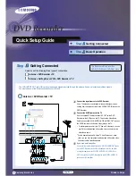
DVD-R100
Brand: Samsung Pages: 4

DVD-R130
Brand: Samsung Pages: 99

D827 MCH
Brand: Studer Pages: 184

LFH0662
Brand: Philips Pages: 2

LFH0620
Brand: Philips Pages: 2

LFH0652/00
Brand: Philips Pages: 21

LFH0645/27
Brand: Philips Pages: 22

LFH0615/00
Brand: Philips Pages: 22

LFH3000
Brand: Philips Pages: 30

LFH4400
Brand: Philips Pages: 36

DPM8000
Brand: Philips Pages: 184

VoiceTracer DVT1115
Brand: Philips Pages: 2

VoiceTracer DVT1120
Brand: Philips Pages: 2

VoiceTracer DVT1160
Brand: Philips Pages: 2

VoiceTracer DVT1110
Brand: Philips Pages: 2

Voice Tracer LFH0632
Brand: Philips Pages: 2

Voice Tracer LFH0633
Brand: Philips Pages: 2

Voice Tracer LFH0645
Brand: Philips Pages: 3


