background image


Raytheon Anschuetz GmbH 
Postfach 11 66 
D-24100 Kiel 
Germany 
Tel +49-4 31-30 19-0 
Fax +49-4 31-30 19 464 
Email [email protected] 
www.raytheon-anschuetz.com 


Edition: February 2020 

4352.DOC010002 


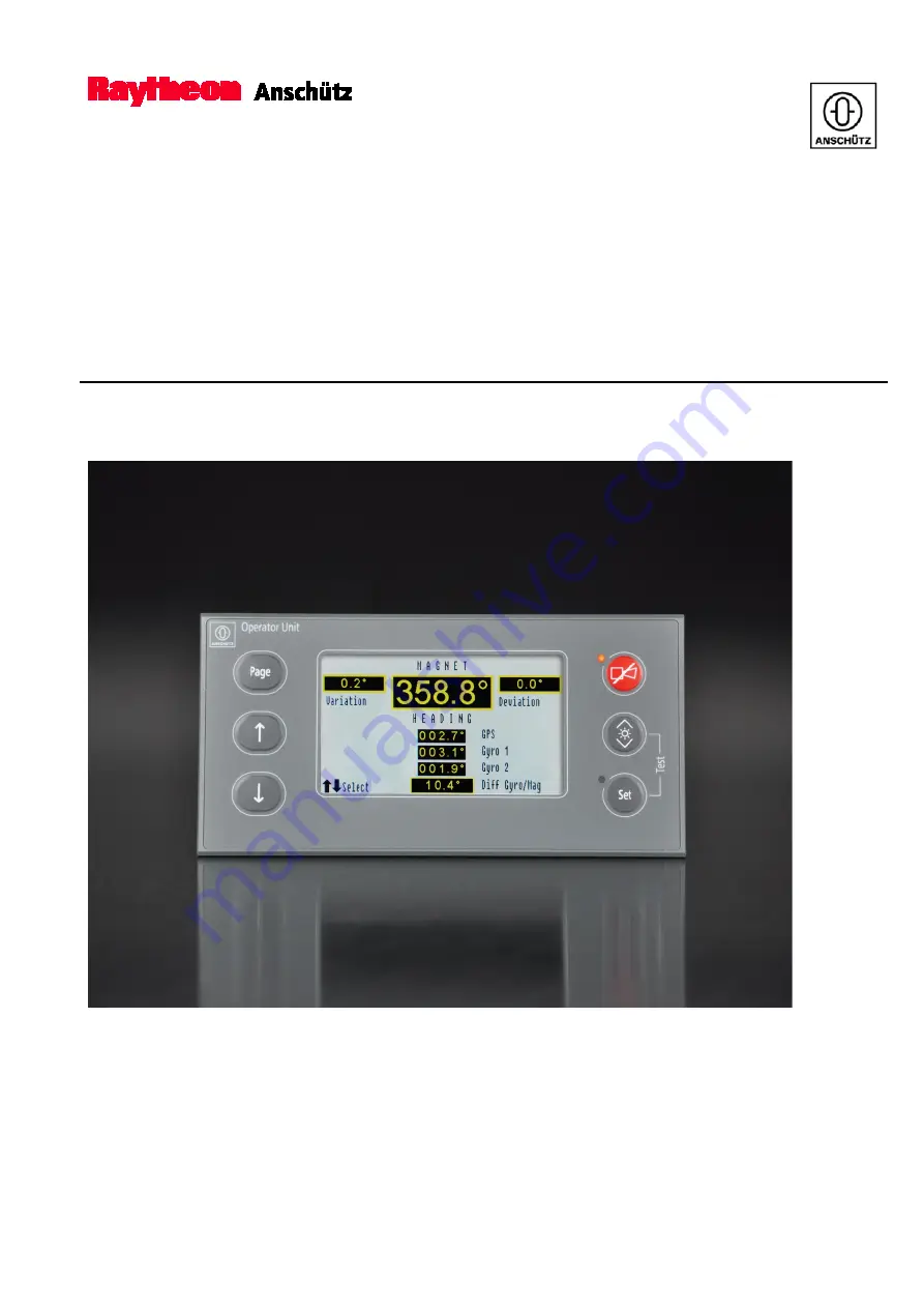
Operator Unit 130-626.NG002 
 
Standard 22 GYRO COMPASS 

Operator and Service Manual 


Summary of Contents for Standard 22 GYRO COMPASS

Page 1: ...66 D 24100 Kiel Germany Tel 49 4 31 30 19 0 Fax 49 4 31 30 19 464 Email service raykiel com www raytheon anschuetz com Edition February 2020 4352 DOC010002 Operator Unit 130 626 NG002 Standard 22 GYRO...

Page 2: ...attet Zuwiderhandlungen verpflichten zu Schadenersatz nderungen dieses Dokuments und dessen Inhalt bleiben vorbehalten This document and its content are copyright protected Distribution reproduction a...

Page 3: ...ughly If you have any further questions please contact us on the following address RAYTHEON ANSCH TZ GMBH Zeyestr 16 24 D 24106 Kiel Germany Tel 49 431 3019 0 Fax 49 431 3019 291 All rights reserved N...

Page 4: ...e with software version E00 03 E00 04 E01 01 E01 02 E00 05 E00 06 added Graphical ROT roll and pitch indication chapter 1 4 4 Latitude input with north south indication required for systems with Stand...

Page 5: ...ng 1 10 1 4 2 2 Speed Error Correction 1 12 1 4 2 3 DV Bus 1 14 1 4 2 4 Speed Source DU 1 15 1 4 2 5 Heading Uncorrected 1 16 1 4 2 6 Rate of Turn 1 17 1 4 2 7 Deviation Table 1 18 1 4 2 8 Gyro Data 1...

Page 6: ...9 4 Change Speed Source DU 2 20 2 9 5 Deviation Table 2 21 2 9 5 1 Deviation Tables in a GG R System 2 21 2 9 6 Select Damping of Rate of Turn 2 22 2 9 7 Set Speed Error Correction 2 22 2 10 Activate...

Page 7: ...0 Heading Uncorrected 1 16 Figure 1 11 Rate of Turn 1 17 Figure 1 12 Deviation Table 1 18 Figure 1 13 Gyro Data 1 19 Figure 1 14 CAN Device 1 20 Figure 1 15 Software Versions Figure may vary from actu...

Page 8: ...lements at the Connection Board 3 14 Figure 3 11 Definition of NMEA Telegram PANZHDS 3 20 Figure 3 12 Definition of NMEA Telegram PANZSLD 3 21 Figure 3 13 Definition of NMEA Telegram PANZDAT 3 21 Figu...

Page 9: ...s are used in this manual WARNING Warning statements indicate a hazardous situation that if not avoided could result in death or serious injury CAUTION Caution statements indicate a hazardous situatio...

Page 10: ...pment and systems Digital interfaces 0 3 List of Abbreviation Term Description BAM Bridge Alert Management BNWAS Bridge Navigational Watch Alarm System CAM HMI Central Alert Management Human Machine I...

Page 11: ...vices non Raytheon devices connected to the distribution unit are not output via the operator unit Only a sensor error would be reported by a timeout CAUTION If there are more than one operator unit i...

Page 12: ...ossible to connect more than one operator unit to the CAN Bus Both operator units connected to the system have the same priority Figure 1 1 Operator Unit Desk Flush Mounted The operator Unit is availa...

Page 13: ...lable Figure 1 2 Operating Elements and Indicators Gyro Compass Selected Pos No Designation Function 1 Select Down Use the Select Down button to navigate through the display 2 Select Up Use the Select...

Page 14: ...LED Flashes whenever an adjustment can be performed 11 Set Use the Set button to confirm the selection adjustment 12 Unselected sensors Displays the heading of the unselected sensors 13 Selection poss...

Page 15: ...distribution units via the CAN Bus Make sure that the receivers are allowed to use the heading information from a magnetic compass 1 4 Main Pages The operator unit provides 4 main pages which can be s...

Page 16: ...g information Speed The last selected mode is selected by default The following modes are available Automatic Speed Aut Speed Manual Speed Man Speed Individual Speed Ind Speed To switchover to Man Spe...

Page 17: ...ring Service Heading Monitoring Within the compass system all connected heading sensors are compared with each other in order to monitor and display the difference of a defined threshold If the sensor...

Page 18: ...February 2020 Gyro compass can be Compass Standard 22 Standard 30 MF or other external non Raytheon Ansch tz heading devices Magnetic compass can be Raytheon Ansch tz magnetic probe or other non Rayth...

Page 19: ...c The service page shows the heading of the selected sensor see Figure 1 5 To open the service mode and the sub menus of the service page see chapter 2 9 1 Every sub menu of the service page except fr...

Page 20: ...1 2 1 and 2 to navigate through the display 2 Remaining Time Shows the remaining time until it switches back to the overview page 3 Back Switches back to the previous page 4 Set Value Confirm the set...

Page 21: ...s to be performed manually For changing the current sensor see chapter 2 7 To change the settings for auto heading see chapter 2 9 2 If an automatic switchover takes place the alert Autom Switched to...

Page 22: ...ro compass systems 1 Manual input of speed and latitude In this application speed and latitude are manually input via the Operator Unit of the gyro compass This data is transferred to all connected St...

Page 23: ...22 no 2 accordingly for speed In this application faulty speed or latitude data affect the heading of only one Standard 22 Advantage Heading monitoring systems or subsequent systems such as DP systems...

Page 24: ...Chapter is for information only This sub menu provides the opportunity to connect a DV Bus to the distribution unit 138 118 and to assign a DV Bus address For a detailed description see manual of the...

Page 25: ...se the speed sensor is not connected to the distribution unit display information by selecting this menu is Not accepted The same happens if no external speed sensor is connected Figure 1 9 Speed Sour...

Page 26: ...ion from the gyro compass and the magnetic compass is displayed Correction values of the gyro compass are speed error correction Correction values of the magnetic compass are variation and deviation U...

Page 27: ...n the distribution unit type 138 118 Figure 1 11 Rate of Turn A positive sign and a green bar stand for a rate of turn to starboard A negative sign and a red bar stand for a rate of turn to port side...

Page 28: ...viates With correction values deviation values the deviation fault can be corrected This correction value is entered via the operation unit to the distribution unit and is used to correct the magnetic...

Page 29: ...pply Supply voltage of the gyro sphere Gyro current Current consumption of the gyro sphere Pump supply Supply voltage of the pump Pump current Current consumption of the pump Sensor PCB Status of Sens...

Page 30: ...he CAN Devices sub menu displays the Unit ID and the CAN Bus status of all devices connected to the CAN Bus Figure 1 14 CAN Device Pos No Designation 1 Unit ID 2 Connected Device 3 CAN Bus Status The...

Page 31: ...GYRO COMPASS Edition February 2020 1 21 4352 DOC010002 First digit 1 CAN Bus Second digit 2 CAN Bus Following CAN Bus statuses are possible 0 No Timeout 1 Timeout 2 unknown device itself For example 0...

Page 32: ...nit P01 Program at the sensor PCB P02 Program at the power PCB P03 Program for MC 1 at the outer sphere PCB P04 Program for MC 1 at the outer sphere PCB P05 Program of the CAN Bus processor DV Bus at...

Page 33: ...or is displayed to provide the possibility to read the heading information from a greater distance Figure 1 16 Heading Pos No Designation Function 1 Heading Shows the heading of the selected sensor 2...

Page 34: ...Pitch Tendency Bar Displays the Pitch value in the tendency bar 6 Pitch Value Displays the Pitch value A positive sign and a green bar stand for a rate of turn or roll to starboard and a pitch forward...

Page 35: ...Designation Function 1 State Shows the priority of the alerts For detailed information see chapter 1 7 2 Alert Text Shows the device and the Unit ID and the alert message see Figure 4 1 For detailed...

Page 36: ...on the configuration see configuration tool The operator unit can also act as a central dimmer meaning that other devices of NautoSteer AS follow the dimming value of the operator unit Precondition f...

Page 37: ...16 is reserved for development purposes Each bus user can send and receive data via the CAN Bus The CAN Bus must be terminated at both ends via an ohmic resistor This terminating resistor is set by ju...

Page 38: ...reduces the cognitive workload of the operator by minimizing the information presented which is necessary to draw attention to and to assess the situation On the bridge alerts are presented on the in...

Page 39: ...at the task station Category B Alerts where no additional information for decision support is necessary besides the information which can be presented at the CAM HMI These alerts can be acknowledged a...

Page 40: ...ing flashing Table 1 5 Alert List Caution Symbol Icon Symbol Description Caution Table 1 6 Alert Signaling Colour Meaning Visual Acoustic Signals Red Alarm flashing Alarms faults and or dangerous situ...

Page 41: ...t are used for speed error correction mode of speed error correction Thresholds for heading monitoring gyro gyro and gyro TMC The compass system is able to receive the following data from INS Number o...

Page 42: ...92 mm Depth 82 mm Weight 1 5 kg Type of Enclosure IP23 back side IP56 front side see Dimensional Drawing 130 626 HP005 higher rating with special casing 1 10 2 Electrical Data Supply Voltage 24 V DC 1...

Page 43: ...2 2 Operation 2 1 Safety Information CAUTION After changes in the configuration of the Speed Error Correction and DV Bus service page the distribution units and the operation units have to be reset Ch...

Page 44: ...inutes after switching on heating stage it is possible to activate the quick settling function see chapter 2 9 6 The switching on process is divided in the following stages May vary depending on the c...

Page 45: ...tent The gyro system is settled after a period of 4 hours for Raytheon Ansch tz Standard 22 Until then the heading information has a reduced accuracy The settling stage is displayed below the heading...

Page 46: ...to navigate through the main pages or to get back to the overview page 4 Speed Displays the speed 5 Selected Sensor Displays the heading of the selected sensor 6 Latitude Displays the latitude 7 Alert...

Page 47: ...ure 2 3 3 to navigate through the 4 main pages 2 3 2 General Settings Change the values Use the Select buttons to navigate through the display and to change values In the left corner of the display a...

Page 48: ...ghtness button again to decrease The brightness decreases as long as the button is pressed The first operation of the button always increases the brightness 2 5 Switchover between Day Mode and Night M...

Page 49: ...longing to the same group has been switched over No The display mode can only be changed at this device Changes of connected devices do not affect this device 2 Display Mode Displays the current previ...

Page 50: ...utton Figure 2 3 11 The Night mode is highlighted 6 Use the Select buttons Figure 2 3 1 and 2 to change the night mode The Display Mode shows the currently previewed mode 7 Confirm the selection of th...

Page 51: ...to use magnetic heading After switching on the operator unit GYRO 1 is selected as the default compass and the heading value is displayed All other connected and displayed heading sensors can be sele...

Page 52: ...tude CAUTION It is recommended to read the information about Individual SEC first before the function Individual Lat is applied 1 Open the overview page see chapter 2 3 1 2 Select Latitude with the Se...

Page 53: ...age see chapter 2 3 1 2 Select Variation with the Select buttons Figure 2 3 1 and 2 3 Press the Set button Figure 2 3 11 to confirm the selection 4 Use the Select buttons Figure 2 3 1 and 2 to switch...

Page 54: ...value for the difference between gyro and magnetic 2 Diff G G Shows and enables the setting of the user threshold value for the difference between gyro and gyro Set the threshold value for the differe...

Page 55: ...Difference Set Switch Over Auto Heading DV Bus Settings Change Speed Source DU Deviation Table Select Damping Set Speed Error Correction 2 9 1 Open the Service Mode If nothing is changed and no sub me...

Page 56: ...uary 2020 Figure 2 8 Open the Service Mode 3 Press the Select Down button Figure 2 3 1 for approx 3 sec to enter the service mode The service mode is activated 4 Press the Up or Down button Figure 2 3...

Page 57: ...igure 2 10 Set Switchover Auto Heading Pos No Designation Function 1 Back Switches back to the previous page 2 Set Value Confirm the settings for auto heading 3 Gyro Selection Decide if an automatic s...

Page 58: ...r enabled No Automatic Switch over disabled 4 Press the Set button to leave the option 5 Use the Set button to set the value and leave the sub menu 1 Set the value Select Set the value Figure 2 10 2 a...

Page 59: ...ection to the Distribution Unit is desired 4 Address Assign a DV Bus address 2 9 3 1 Connect DV Bus CAUTION After changes in the configuration of the DV Bus service page the operator units has to be r...

Page 60: ...DV Bus enabled No DV Bus disabled 4 Use the Set button to set the value and leave the sub menu 1 Set the value Select Set the value and press the Set button to confirm If values have been changed the...

Page 61: ...1 and 15 is possible 1 Open the sub menu DV Bus from the service page see chapter 2 9 1 The sub menu DV Bus opens see Figure 2 11 2 Use the Set button Figure 2 3 11 to navigate to Address Figure 2 11...

Page 62: ...f Individual Speed the speed source must be adjusted by DIP Switches at the gyro compass itself Figure 2 12 Speed Source DU Table 2 2 Speed Source DU Display Description Puls Log VHW Water speed and h...

Page 63: ...o navigate through the options 1 Edit value and set value A correction value can be edited and or set 2 Erase value Erases a selected value 3 Erase all values Erases all correction values of the devia...

Page 64: ...tion unit 138 118 is connected The damping of the RoT is not possible if the distribution unit 138 126 is connected 1 Open the sub menu Rate of Turn from the service page see chapter 2 9 1 The sub men...

Page 65: ...es are not available for speed error correction only the manual and individual values are available 6 Use the Set button Figure 2 3 11 to go to the option Individual 7 Change the option to Yes or No w...

Page 66: ...ck settling function can only be used if the ship s heading has not been changed between switching off and switching back on The quick settling function cannot be used For first setting into operation...

Page 67: ...mpass If several max 3 gyro compasses should be activated with the quick settling function it is recommended to switch on the compasses one after another in order not to exceed the three minutes After...

Page 68: ...which are available for quick settling are listed see Figure 2 18 Figure 2 18 Quick Settling Available Gyros Listed 3 Select the gyro compass to be quick settled with select buttons 4 Press the set bu...

Page 69: ...p test during an alert is not possible Alerts are not displayed during a lamp test Figure 2 20 Lamp Test Pos No Designation 1 Brightness 2 Set 1 Press the brightness button Figure 2 20 1 and the set b...

Page 70: ......

Page 71: ...d refer to Dimensional Drawing 130 626 HP005 WARNING When establishing cable connections ensure that the cables are disconnected from any power supply It is essential to ensure that all cables are dis...

Page 72: ...11 NG002 E01 The operator unit must be configured before setting into operation This configuration can be performed with the Configuration Tool AS only Voltage supply and connections as well as the bu...

Page 73: ...0 mm Be careful not to damage the screening 2 Trim the screening until approx 15 mm is on the cable Figure 3 1 Strip off the Cable Connection The cable length to strip off must be adapted to the lengt...

Page 74: ...ition February 2020 Shrinking sleeves must be used However do not strip the shrinking sleeve over the screening Figure 3 2 Proper Cable Connection Example Only It is recommended to fasten the connecte...

Page 75: ...parate power switch When establishing cable connections ensure that the cables are disconnected from any power supply It is essential to ensure that all cables are disconnected from the power supply i...

Page 76: ...B7 and B8 The termination of the CAN Bus depends on its application within a compass system Figure 3 4 Connect CAN Bus at Plugs B7 and B8 Table 3 2 Connect CAN Bus at Plugs B7 and B8 Plug terminal Rem...

Page 77: ...3 7 4352 DOC010002 3 3 3 Connect Status Output System Failure at Plug B4 Figure 3 5 Connect Status Output SYSTEM FAILURE at plug B4 Table 3 3 Connect Status Output SYSTEM FAILURE at plug B4 Plug term...

Page 78: ...g B5 Figure 3 6 Connect Serial In and Serial Out at Plug B5 Table 3 4 Connect Serial In and Serial Out at Plug B5 Plug terminal Remarks RS422 RS485 B5 1 TX B B5 2 TX A B5 3 Ground Ground B5 4 RX N C B...

Page 79: ...nect Relay Switching Outputs 1 to 4 at Plugs B6 and B11 Table 3 5 Connect Relay Switching Outputs 1 to 4 at Plugs B6 and B11 Plug terminal Remarks B6 1 B11 1 B6 3 B11 3 B6 2 B11 2 B6 4 B11 4 B6 6 B11...

Page 80: ...6 Connect the Digital Inputs 1 and 2 at Plug B10 Figure 3 8 Connect the Digital Inputs 1 and 2 at Plug B10 Table 3 6 Connect the Digital Inputs 1 and 2 at Plug B10 Plug terminal Remarks B10 1 B10 3 Di...

Page 81: ...r serial in and serial out Baud rate for serial in and serial out Heartbeat telegram on off Type of alert communication ALR ACK or ALF ALC ACN ACR Serial interface alert and or remote A special config...

Page 82: ...lements of the CPU PC Board and the Connection PC Board Figure 3 9 Operation and Display Elements of the CPU PC Board Pos No Designation Function 1 DIP Switch B11 Development only 2 Push button B7 Pus...

Page 83: ...e 6 Push button B8 LED H8 LED H12 Push button ACK with illumination LEDs white 7 LED H7 LED ALERT red or green red means flashing An alert is active and must be acknowledged constant An already acknow...

Page 84: ...rd Pos No Designation Function 1 Plug B4 Relay Output System Failure Interactive relay system fail Active relay operation okay 2 Plug B9 24V DC supply voltage input 3 LED H1 Lights up red if System Fa...

Page 85: ...elay Switching Output 2 Out 1 Alert to BNWAS Out 2 Currently not used 12 Plug B11 Relay Switching Output 3 and Relay Switching Output 4 Out 3 4 Currently not used 13 LED H5 Lights up green if Relay Sw...

Page 86: ...17 Must be used in simultaneously only If they are switched the input SIN1 serial in RS422 is switched off and the output terminals of plug B5 for RS422 Out are used for data in out for a RS485 interf...

Page 87: ...mmunication at the same time But to ensure the correct repetition rates it is recommended to use the interface only for Alert or Remote communication The following telegrams can be used for receiving...

Page 88: ...ate Set Alarm State ALR 1 s Alert Sentence ALF In the event of changes or on demand Cyclic Alert List ALC 20 s or in the event of changes Alert Command Refused ACR Answer to ACN if request was refused...

Page 89: ...ud rates can be used 4800 Bd 9600 Bd 19200 Bd 38400 Bd Only the baud rates 4800 and 38400 are conform to IEC 61162 Select the following connection settings Data bit 8 Parity no Stop bit 1 The Operator...

Page 90: ...heading fields can be empty NULL if the sensor does not exist The selected sensor field must not be empty In total 4 sensors are allowed e g 3 Gyro TMC or 2 Gyro GPS THD TMC This telegram can also be...

Page 91: ...o external system PANZDAT heading difference alert thresholds heading monitoring This telegram contains the thresholds for the Gyro Gyro and the Gyro TMC difference alert heading monitoring function F...

Page 92: ...120 or 121 7 56 or 57 CAN Bus Distributor 51 56 2 51 56 Some older devices which are not adjustable by the Configuration Tool AS only by DIP Switch or Hex Switch e g Standard 22 Distribution Unit can...

Page 93: ...oting 4 1 Safety Information CAUTION After re connection of interfaces it takes up to 30 seconds until the correct values are displayed again It is possible that an unacknowledged warning escalates to...

Page 94: ...ber 2 Unit ID 3 Alert Message Alert Message Possible Cause Remedy Autom Switched to XXX1 Sw to XXX1 Sensor error Switch over manually CAN Bus line X1 failure CAN X1 Short circuit at CAN line Check CAN...

Page 95: ...electronic Check RoT sensor and connections Sensor Error Sens Err Defect of electronic Check sensor and select other sensor if necessary If magnetic is selected no valid selected sensor in system Spe...

Page 96: ...igational Watch Alarm System BNWAS The operator unit provides an interface to the bridge navigational watch alarm system BNWAS Alert escalation If alarm messages are not acknowledged and the reason fo...

Page 97: ...5 1 4352 DOC010002 5 Maintenance and Repair The Operator Unit is maintenance free In case of malfunction the Operator Unit has to be replaced completely The function test should be performed only if a...

Page 98: ...Operator Unit 130 626 NG002 Standard 22 GYRO COMPASS 4352 DOC010002 5 2 Edition February 2020 Intentionally left blank...

Page 99: ...2020 6 1 4352 DOC010002 6 Disposal The Operator Unit or components of it can be disposed according to the respective national regulations for electronic waste without harmful material according to 20...

Page 100: ...Operator Unit 130 626 NG002 Standard 22 GYRO COMPASS 4352 DOC010002 6 2 Edition February 2020 Intentionally left blank...

Page 101: ...82 1 3 24 0 039 178 1 7 008 0 039 74 1 2 913 0 039 4x 5 0 5 0 197 0 019 166 0 2 6 535 0 007 82 0 2 3 228 0 007 DISTANCE FROM MAGNETIC COMPASS STANDARD TYPE STEERING TYPE 0 65 m 0 35 m Pro E 5026339 ca...

Page 102: ......

Page 103: ......

Page 104: ......

Reviews: