background image

© 2017 Raymarine UK Limited

81370-1

Document number:

04-2017

Date:

English (en-US)

Advanced operation instructions

Summary of Contents for AXIOM

Page 1: ...2017 Raymarine UK Limited 81370 1 Document number 04 2017 Date English en US Advanced operation instructions...

Page 2: ......

Page 3: ...ts design patents patents pending or design patents pending Fair Use Statement You may print no more than three copies of this manual for your own use You may not make any further copies or distribute...

Page 4: ......

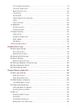
Page 5: ...Data sources 18 Identifying engines 19 Configuring Transducer settings 19 3 2 Inserting a MicroSD card 20 Removing a MicroSD card 20 Memory card compatibility 20 3 3 Shortcuts 21 Adjusting brightness...

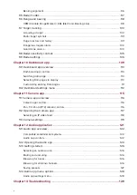
Page 6: ...ter 5 General app settings 43 5 1 Sidebar 44 Customizing Sidebar data 44 5 2 Data overlays 45 5 3 Editing the split ratio of a Splitscreen app page 46 5 4 App settings menus 47 Chapter 6 Waypoints Rou...

Page 7: ...76 Sonar app controls 76 RealVision 3D controls 77 8 2 Opening the Sonar app 78 8 3 Sonar channels 81 Selecting a Sonar channel 81 8 4 Placing a Waypoint in the Sonar app 82 8 5 Sonar sensitivity cont...

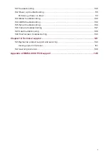
Page 8: ...10 Customizing existing Data pages 111 10 2 Dashboard settings menu 112 Chapter 11 Camera app 115 11 1 Camera app overview 116 Camera app controls 116 Pan Tilt Zoom PTZ camera controls 116 11 2 Openin...

Page 9: ...troubleshooting 133 13 5 Sonar troubleshooting 134 13 6 Camera troubleshooting 137 13 7 Data troubleshooting 139 13 8 Touchscreen troubleshooting 140 Chapter 14 Technical support 141 14 1 Raymarine p...

Page 10: ...10...

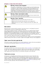
Page 11: ...ages or injuries caused by your use or inability to use the product by the interaction of the product with products manufactured by others or by errors in chart data or information utilized by the pro...

Page 12: ...12...

Page 13: ...Chapter 2 Document and product information Chapter contents 2 1 Product documentation on page 14 Document and product information 13...

Page 14: ...dvanced operation instructions 81370 RMK 10 Remote Keypad Installation and operation instructions 81367 RMK 9 Remote Keypad Installation and operation instructions 81351 Software revision Product soft...

Page 15: ...tents 3 1 Getting started on page 16 3 2 Inserting a MicroSD card on page 20 3 3 Shortcuts on page 21 3 4 Software updates on page 22 3 5 Device pairing on page 23 3 6 Performing a settings or factory...

Page 16: ...red Data sources if required 6 Perform Engine identification if required 7 Select check Transducer settings if required Powering on the display When power is available to the MFD but the MFD is switch...

Page 17: ...master If you are connecting to a network that already includes MFDs then on first power up you will be requested to confirm your Data master The Multiple Data masters found warning will be displayed...

Page 18: ...ed readings Heading Enables you to choose a source of data for Heading data GPS Enables you to choose a source of data for GPS data GPS Datum In order for your GNSS receiver and MFD to correlate accur...

Page 19: ...systems set up with Sonar you should configure your transducer settings 1 Select Transducer from the Sonar app s Settings menu Menu Settings Transducer 2 Select how you want your depth to appear i Be...

Page 20: ...d format MFD supported Format MicroSDSC Micro Secure Digital Standard Capacity Up to 4GB FAT12 FAT16 or FAT16B NTFS FAT32 MicroSDHC Micro Secure Digital High Capacity 4GB to 32GB FAT32 NTFS FAT32 Micr...

Page 21: ...save the image to external memory 1 Swipe your finger from left to right across the Power button swipe area The Shortcuts menu is displayed 2 Select Take screenshot The screenshot will be saved in png...

Page 22: ...Settings Getting started 2 Check the latest available software on the Raymarine website www raymarine com Support Software Updates 3 Download the software package 4 Copy the files to MicroSD card 5 I...

Page 23: ...keypad for details on operating your MFD with the keypad Clear pairing RMK 1 Select Clear pairings to remove pairing for ALL RMK keypads that are paired with the MFD Pairing with a Quantum Radar scan...

Page 24: ...rming a Settings reset will restore your MFD s settings to factory defaults whilst retaining user data 1 Select Settings reset from the This display tab Homescreen Settings This display Settings reset...

Page 25: ...een overview on page 27 4 3 Creating Customizing an App page on page 28 4 4 User profiles on page 29 4 5 My data on page 31 4 6 Settings on page 33 4 7 Man Overboard MOB on page 36 4 8 Alarms on page...

Page 26: ...cept the Limitations on Use LoU disclaimer To view the full LoU Disclaimer select more details The LoU acknowledgment is displayed each time the display is powered on and for each new user profile The...

Page 27: ...st the UTC time offset 4 App page icons Select an icon to open the relevant application page Use the Left and Right arrows or swipe your finger left or right across the area to cycle through the avail...

Page 28: ...rom the Popover options to change page layout and apps used To Create a new page press and hold on a blank space on the Homescreen 3 Select the Layout option to change the page layout 4 Select the ico...

Page 29: ...ettings changes are unique to the profile in use and are retained the next time the profile is used The distance and time that a profile has been active is displayed for each profile Profile names and...

Page 30: ...o help you practice operating your display Important It is recommended that Demo profiles are NOT activated whilst navigating Demo profiles will NOT display any real data including safety warnings and...

Page 31: ...ere you can manage and customize your data Selecting Trip will display the trip counters Selecting Reset man trip will reset the Trip counter to zero Selecting Files opens a file browser Selecting Imp...

Page 32: ...ved to internal or external storage and can also be used to import or delete gpx User data files from internal or external storage Select a device to view its contents Select an image file to view or...

Page 33: ...for screenshots Pair unpair with a RMK external keypads Pair with a wireless Quantum Radar scanner Perform a Settings or Factory reset Network View list of networked MFDs Assign a MFD Data master Vie...

Page 34: ...to a compatible system your MFD can monitor engine data Identify engines Once you have selected the number of engines select Identify engines and follow the onscreen instructions to configure your eng...

Page 35: ...oints Routes and Tracks Radar Sonar Data received from the autopilot GNSS receiver instruments transducers the engine and any other compatible external sources Note Your system may be wired for redund...

Page 36: ...led a MOB Databar providing Bearing and range from MOB and elapsed time since MOB was initiated is placed along the top of the screen The Databar persists across apps and the Homescreen and remains un...

Page 37: ...display audible and visual warnings The onscreen warning provides details of why the alarm has been triggered Example Waypoint arrival alarm The Alarm manager can be used to list current active alarms...

Page 38: ...ge shows the position of navigation satellites and the constellation they belong to The color of the satellite identifies its status Grey searching for satellite Green satellite in use Orange tracking...

Page 39: ...D s internal GNSS receiver Disable if you do not want to use this unit s internal GNSS receiver as a source for positioning data restart the GNSS receiver that is being used as the source for your pos...

Page 40: ...dar Sonar module Transducer Popover menu options From the Options popover you can Switch your AIS transceiver between transmitting and silent mode Disable Radar transmission Adjust the Time offset fro...

Page 41: ...us Sonar pinging Wi Fi connected signal strength High Sonar not pinging Wi Fi connected signal strength Medium Sonar error Wi Fi connected signal strength Low Touchlock active Wi Fi not connected Wi F...

Page 42: ...42...

Page 43: ...eneral app settings Chapter contents 5 1 Sidebar on page 44 5 2 Data overlays on page 45 5 3 Editing the split ratio of a Splitscreen app page on page 46 5 4 App settings menus on page 47 General app...

Page 44: ...the left edge of the screen Swiping right to left will hide the Sidebar To customize the displayed data press and hold on the Data item you want to change and select Edit from the Popover options Cus...

Page 45: ...an be placed over any app in a Splitscreen app page Data overlays can be customized from Menu Settings Page Settings Edit data overlays In edit mode drag the data overlay to the desired location then...

Page 46: ...Splitscreen app page With a Splitscreen app page displayed 1 Select Edit split ratio from the Page settings tab Menu Settings Page settings Edit split ratio 2 Drag the Resize icon to create the desir...

Page 47: ...5 4 App settings menus Each app includes a settings menu that provides access to app settings and features The settings menu in each app is signified by the Settings icon General app settings 47...

Page 48: ...48...

Page 49: ...Chapter 6 Waypoints Routes and Tracks Chapter contents 6 1 Waypoints on page 50 6 2 Routes on page 53 6 3 Tracks on page 56 Waypoints Routes and Tracks 49...

Page 50: ...n and select Place waypoint from the context menu 2 Select Edit to edit the waypoint details Goto to navigate to the Waypoint or OK to return to normal operation To place a waypoint at your vessel s c...

Page 51: ...app Homescreen My data Waypoints or Chart app Menu Waypoints routes tracks Waypoints Waypoint list The Waypoint list is sorted into groups Selecting a group displays a list of all the waypoints inclu...

Page 52: ...t you can change the list sort order Hide Show the Waypoint group in the current Chart app instance or create a New waypoint Use the Multi edit option to make the same change to multiple Waypoints e g...

Page 53: ...oute 4 Select the location for subsequent waypoints 5 Check your Route will be safe to follow you can move the waypoints in your route by dragging them to a new location 6 When your Route is complete...

Page 54: ...the route s location From the Route plan you can navigate the route by selecting Follow change the route direction by selecting Reverse add an existing waypoint to the route by selecting Add waypoint...

Page 55: ...rrival and TTG Time To Go Speed Switch the speed between Actual SOG and Planned When the speed is set to Planned you can select a desired speed for navigating the route Hide show on chart Choose wheth...

Page 56: ...rack You can also start a new track recording at anytime from the Chart menu Menu New Start a new track When using the Chart menu to start a track if a track is already recording then it will be saved...

Page 57: ...ce or set to Auto In Auto the track interval is set automatically to minimize the track points used whilst maintaining the actual path taken When set to Time you can choose a specified time period bet...

Page 58: ...58...

Page 59: ...Chapter 7 Chart app Chapter contents 7 1 Chart app overview on page 60 7 2 Navigation on page 66 7 3 Target tracking on page 67 7 4 Chart settings menu on page 71 Chart app 59...

Page 60: ...sel icon Represents your vessel only displayed when GNSS position fix is available icon will be a black dot if no Heading is available 4 Wind indicator Provides indication of wind direction and speed...

Page 61: ...the onscreen Range controls or by using the pinch to zoom multi touch gesture You can pan the chart area by swiping your finger across the chart Chart app context menu Context menus provide context se...

Page 62: ...at can be used to quickly set up the Chart app for your intended use DETAILED This is the default chart mode Full menu options are available and any changes made are saved to the user profile in use F...

Page 63: ...change the symbol used to represent your vessel set the length of vessel vectors show hide Heading and COG vectors show hide Range Rings show hide Tide and Wind graphics Object selection and informati...

Page 64: ...w its details In areas where there is a high concentration of charted objects selecting Nearby objects from the context menu will display a list of objects located nearby for you to choose from Layers...

Page 65: ...Chart motion controls how the chart and boat are drawn to keep the boat onscreen as you move Chart orientation The orientation of the chart affects the alignment of the chart relative to your vessel...

Page 66: ...or Menu Go Lat long Restarting cross track error XTE A cross track error XTE occurs when your actual route diverges from your original planned route Restarting XTE plots a new course directly from yo...

Page 67: ...int of approach and TCPA Time to Closest Point of Approach values AIS list The AIS target list popover options enable you to View full target data or add a target as an AIS buddy by selecting Add as b...

Page 68: ...rs can be set to All displayed for all targets or Manual only displayed when turned on using the target s context menu Target vectors can be enabled and disabled for individual targets by pressing and...

Page 69: ...dar scanner transmitting or put it in Standby On Off Dual range Enables and disables dual range on compatible Radar scanners On Off Channel When Dual range is active you can switch between channels 1...

Page 70: ...ns Hide static targets When enabled AIS target travelling under 2 knots will be hidden unless they are or become dangerous On Off Silent mode When enabled your vessel s AIS will not transmit your posi...

Page 71: ...e Chart app On Off All Community edits Allows you to overlay community edits on your compatible cartography On Off Navionics Tides When using compatible cartography enables you to view tide and curren...

Page 72: ...e of the screen the chart is redrawn to reveal the area in front of your vessel Auto range In Auto range the largest possible scale is maintained that will display both your vessel and the destination...

Page 73: ...as Marine features Land features Business services Roads Additional wrecks Colored seabed areas Chart appearance The settings that are displayed are dependent on the cartography in use 2D shading Aeri...

Page 74: ...74...

Page 75: ...1 Sonar app overview on page 76 8 2 Opening the Sonar app on page 78 8 3 Sonar channels on page 81 8 4 Placing a Waypoint in the Sonar app on page 82 8 5 Sonar sensitivity controls on page 83 8 6 Sona...

Page 76: ...ach instance of the Sonar app you can select which Sonar module and channel that you want to use the Sonar module and channel selection will persist over a power cycle The Sonar app can be displayed i...

Page 77: ...ge Zoom Out When in Zoom mode pressing the minus icon will decrease the Zoom factor and finally revert to normal mode When Range is set to Manual pressing the Minus icon increases the distance display...

Page 78: ...you have installed your Sonar module in accordance with the documentation that was supplied with the module The Sonar app will open in 1 of 4 states Please select a sonar channel The first time you o...

Page 79: ...sonar module s network and power connection check your MFD s network or transducer connection ensuring the connections and cabling is correct and free from damage then power cycle your system If the...

Page 80: ...ucer connection s are correct and free from damage then power cycle your system If the transducer is still not found then refer to your equipment s installation documentation for further troubleshooti...

Page 81: ...uency Low CHIRP Low Frequency Selecting a Sonar channel The first time you open a new Sonar app page you will be requested to select a channel subsequently you can change the sonar channel by selectin...

Page 82: ...interest onscreen The Context menu is displayed and scrolling is paused temporarily 2 Select Add Waypoint from the context menu The Sonar image will remain paused for approximately 10 seconds after t...

Page 83: ...it for the color used for the strongest target returns All target returns above this value are displayed in the strongest color Those with a weaker value are divided equally between the remaining colo...

Page 84: ...n Off Bottom fill Displays a solid color fill for the bottom On Off Color threshold Color threshold determines the signal strength below which target returns are not shown A low value results in only...

Page 85: ...to rename your sonar module Onscreen keyboard Ping enable Enables and disables transducer ping On Off Ping rate limit Allows you to restrict the transducer s maximum ping rate to suit current conditio...

Page 86: ...by signal reflection Off Low High Reset sounder Resets the sonar module to factory default settings Yes No Reset trip In installations that include a speed transducer connected via the sonar module a...

Page 87: ...Radar feature comparison on page 90 9 3 Opening the Radar app on page 93 9 4 Set up on page 95 9 5 Radar modes on page 97 9 6 Range and bearing on page 98 9 7 Target tracking on page 100 9 8 Radar se...

Page 88: ...p you can select which Radar scanner you want to use the Radar scanner selection will persist over a power cycle The Radar app can be displayed in both Fullscreen and splitscreen app pages App pages m...

Page 89: ...app context menu Context menus provide context sensitive menu options Context menus are accessed in the Radar app by selecting a location or target The context menu provides Latitude longitude range a...

Page 90: ...Radome Power Boost SuperHD Open Array Antenna Boost SuperHD Open Array Gain Modes Features settings Radar type Buoy SuperHD Open Array HD Open Array HD Radome Harbor All Coastal All Offshore All Bird...

Page 91: ...Size selection SuperHD Open Array 4ft 6ft HD Open Array 4ft 6ft Timed Transmit All Bearing Alignment All MBS Main Bang Suppression Off All Tuning Preset SuperHD Open Array HD Open Array HD Radome Dig...

Page 92: ...Compatible Radar scanners The table below lists Radar scanners that can be used with the Radar app Quantum SuperHD Open Array HD Open Array HD Radome Digital Radome 92...

Page 93: ...he Off Not Connected message is displayed then your Radar scanner may be powered down or your MFD cannot establish a connection with your Radar scanner Select On to power up your Radar If the Radar no...

Page 94: ...onscreen Putting the Radar into Standby With your selected Radar displayed onscreen 1 Select Transmit from the main menu The Radar scanner will stop transmitting and is put into Standby mode Powering...

Page 95: ...ill change to display the selected Radar scanner Radar scanner selection shall persist over a power cycle Alternatively with the Radar powered off or in Standby you can select switch Radar scanner by...

Page 96: ...erform The Radar will transmit for the specified number of rotations and then will switch to Standby for the specified time interval the sequence will repeat until Timed Transmit is switched off The T...

Page 97: ...Radar scanners SuperHD Open Array HD Open Array and HD Radome COASTAL Coastal mode takes into account slightly higher levels of Sea clutter that are encountered out of Harbor areas This mode is usefu...

Page 98: ...eparation distance Range identifies the distance from your vessel to the top edge of the screen Rings identifies the distance between each Range Ring The displayed range can be adjusted at anytime usi...

Page 99: ...RM EBL to determine the range and bearing between 2 targets Editing a VRM EBL Once a VRM EBL has been placed you can adjust its size and position 1 Select Edit VRM EBL from the context menu 2 To adjus...

Page 100: ...from your vessel Bearing and where relevant CPA Closest point of approach and TCPA Time to Closest Point of Approach values The Radar target list can be Sorted By target Number or its Range from your...

Page 101: ...et not detected for 4 Radar scans Gray circle with Red cross through Once acquired the target s COG Course Over Ground and SOG Speed Over Ground can be displayed below the target ID The Target info is...

Page 102: ...tor length popover options Additional CPA and target information can be displayed for each target using the context menu select a target to display the context menu Target history Target history plots...

Page 103: ...specified Safe distance from your vessel within the time period selected You can select whether you want the Dangerous target alarm to track Radar targets You can display a Safe distance ring around y...

Page 104: ...the Guard Zone Adjust the guard zone size by dragging the inner and outer perimeter end points circles to the desired locations Once configure select Back If required you can also adjust the Guard zon...

Page 105: ...Radar screen as lots of small echoes which continuously change size intensity and position The Rain control suppresses these echoes making it easier to identify real object The higher the Rain contro...

Page 106: ...nsmitting in Time transmit mode 10 scans 20 scans 30 scans View Motion tab Settings Description Options Orientation Head up The top of the screen always points towards your vessel s current heading an...

Page 107: ...ference rejection Suppresses interference from other close by Radar scanners On Off Interference rejection level Determines the level of suppression used Only available when Interference rejection is...

Page 108: ...necessary to adjust Advanced settings Settings Description Options Tune preset Radar tuning is controlled either automatically or manually using the Tune adjust setting Tune preset controls the range...

Page 109: ...Chapter 10 Dashboard app Chapter contents 10 1 Dashboard app overview on page 110 10 2 Dashboard settings menu on page 112 Dashboard app 109...

Page 110: ...izable data pages Dashboard app controls Icon Description Function Home icon Takes you to the Homescreen Menu icon Opens the app menu Waypoint MOB Place waypoint activate Man overboard MOB alarm Left...

Page 111: ...h page can be changed 1 Select and hold on the relevant Data item 2 Select Edit from the Data item popover menu 3 Select the new Data item that you want to display Alternatively you can select Customi...

Page 112: ...ct support for more details Displays file browser Circuits tab Settings Description Options List of tripped channels In Digital Switching systems the Circuit tab provides a list of tripped channels Tr...

Page 113: ...RPM for your engine dials or allow the system to automatically configure the Maximum RPM Auto 3 000 RPM to 10 000 RPM Custom RPM Red zone You can create a custom Red zone for your RPM dials 0 RPM to...

Page 114: ...114...

Page 115: ...Chapter 11 Camera app Chapter contents 11 1 Camera app overview on page 116 11 2 Opening the Camera app on page 117 11 3 Camera settings on page 119 Camera app 115...

Page 116: ...n Description Function Home icon Takes you to the Homescreen Menu icon Opens the app menu Waypoint MOB Place waypoint activate Man overboard MOB alarm Record Start recording Replaced by Stop icon whil...

Page 117: ...o finish booting before the video feed is displayed Camera feed displayed If your camera is powered up and operational then the Camera s video feed is displayed Camera not yet available The camera xxx...

Page 118: ...ctions to your camera and MFD are correct and free from damage and then power cycle your system If the camera feed is still not displayed refer to your equipment s installation documentation for furth...

Page 119: ...use this setting to switch the camera s light on and off On Off Scene The Scene presets provide settings that have been optimized for different running conditions Day Night Docking High contrast Cont...

Page 120: ...the waterline must be set 0ft to 99ft Set forward position Allows you to adjust the Forward position for you camera Adjust the camera so that it is point in forward and select Save to set the forward...

Page 121: ...12 Audio application Chapter contents 12 1 Audio app overview on page 122 12 2 Opening the Audio app on page 124 12 3 Getting started on page 126 12 4 Audio app menu options on page 128 Audio applicat...

Page 122: ...app Only the Entertainment system that you want to control should be connected to the network Compatible entertainment systems The table below shows compatible NMEA 2000 entertainment systems that hav...

Page 123: ...ns Off Tune Up Manually searches up for radio stations channels Tune Down Manually searches down for radio stations channels Repeat Off Repeat Track Repeat All Shuffle On Off Play Select to commence p...

Page 124: ...e with the documentation that was supplied with the system The Audio app will open in 1 of 3 states Note If the Audio app is opened soon after powering on your MFD then the No audio device found messa...

Page 125: ...r Entertainment system Ensure network and power connections to your Entertainment system and MFD are correct and free from damage and then power cycle your system If the Entertainment system is still...

Page 126: ...u can browse USB and Bluetooth devices for tracks With the relevant USB or Bluetooth device selected as the audio source 1 Select Tracks from the Menu The file browser is displayed 2 Alternatively you...

Page 127: ...n be saved for each Radio audio source i e AM Radio FM Radio Weather SiriusXM and Pandora 1 Whilst listening to the station you want to save press and hold the relevant Preset button for approximately...

Page 128: ...ther Sirius XM Pandora Auxiliary USB Bluetooth Power Enables you to Power your Entertainment system on and off On Off Displays the Settings page Audio setting Page settings Audio app settings menu Aud...

Page 129: ...p troubleshooting on page 131 13 3 Radar troubleshooting on page 132 13 4 GNSS troubleshooting on page 133 13 5 Sonar troubleshooting on page 134 13 6 Camera troubleshooting on page 137 13 7 Data trou...

Page 130: ...oducts are subjected to comprehensive testing and quality assurance programs If you do experience problems with your product this section will help you to diagnose and correct problems in order to res...

Page 131: ...ion instructions have been followed Power source insufficient With the product under load using a multi meter check the power supply voltage as close to the unit as possible to establish actual voltag...

Page 132: ...oduct to re boot loose power replace if necessary 4 Check the vessel s battery voltage the condition of the battery terminals and power supply cables ensuring connections are secure clean and free fro...

Page 133: ...xternal GNSS connections and cabling are correct and fault free External GNSS receiver in poor location e g Below decks Close proximity to transmitting equipment such as VHF radio Ensure GNSS receiver...

Page 134: ...sary Wrong transducer fitted Check product and transducer documentation and ensure that the transducer is compatible with your system External sonar module SeaTalkhs RayNet network problem Check that...

Page 135: ...and recheck Poor problematic image Possible causes Possible solutions Targets will appear differently if your vessel is stationary e g fish will appear on the display as straight lines Increase vessel...

Page 136: ...ed or fouled transducer Check the condition of the transducer ensuring it is not damaged and is free from debris fouling Damaged transducer cable Check that the transducer cable and connection is free...

Page 137: ...if this causes the unit to re boot loose power replace if necessary Problem with power supply to the camera or thermal camera s JCU if used as the primary controller Check the power connections to the...

Page 138: ...mera app are set too low Check Camera brightness and contrast adjust if necessary The Scene Mode is not appropriate for the current conditions When viewing a thermal camera feed a particular environme...

Page 139: ...ay or engine interface Check power to the data bus Software mismatch between equipment may prevent communication Check the Raymarine website and ensure all your Raymarine products have the latest soft...

Page 140: ...able TouchLock using the power button Screen is not being operated with bare fingers for example gloves are being worn Bare fingers must make contact with the screen for correct operation Alternativel...

Page 141: ...Chapter 14 Technical support Chapter contents 14 1 Raymarine product support and servicing on page 142 14 2 Learning resources on page 144 Technical support 141...

Page 142: ...ir flir com Web support Please visit the Support area of the Raymarine website for Manuals and Documents http www raymarine com manuals FAQ Knowledgebase http www raymarine com knowledgebase Technical...

Page 143: ...437 164 64 support dk raymarine com Raymarine subsidiary Russia 7 495 788 0508 info mikstmarine ru Authorized Raymarine distributor Viewing product information The Getting started tab contains hardwa...

Page 144: ...nge of in depth training courses to help you make the most of your products Visit the Training section of the Raymarine website for more information http www raymarine co uk view id 2372 FAQs and Know...

Page 145: ...Distance Log 129025 Position Rapid Update 129026 COG SOG Rapid Update 129029 GNSS Position Data 129033 Time Date 129038 AIS Class A Position Report 129039 AIS Class B Position Report 129040 AIS Class...

Page 146: ...vironmental Parameters 130311 Environmental Parameters 130576 Small Craft Status 130577 Direction Data 130578 Vessel Speed Components Raymarine provides field programmability of the Device and System...

Page 147: ......

Page 148: ......

Page 149: ...t Routes 32 Tracks 32 Waypoints 32 External devices 40 F First power up 16 Follow 66 Fuel tank selection 34 G GNSS 38 GNSS GPS Settings 38 GNSS GPS troubleshooting 133 Goto waypoint 66 GPS 38 H Homesc...

Page 150: ...vity controls 83 Surface filter 83 TVG Time Varied Gain 83 Zoom mode 77 Startup wizard 17 Status area 40 Status icons 40 Switching off 16 Switching on 16 System Datum 113 T Technical support 142 Tempe...

Page 151: ......

Page 152: ...Raymarine Marine House Cartwright Drive Fareham Hampshire PO15 5RJ United Kingdom Tel 44 0 1329 246 700 www raymarine com a brand by...

Reviews: