Rangemaster 90 Induction Cooker U109976 - 02, Installation And User Manual
The Rangemaster 90 Induction Cooker U109976 - 02 is a top-of-the-line kitchen appliance for any avid chef. With its sleek design and innovative induction technology, this cooker offers precision cooking at your fingertips. Make sure to download the free Installation And User Manual from our website for easy setup and usage guidelines.
Share
Download


Reviews:
No comments
Related manuals for 90 Induction Cooker U109976 - 02
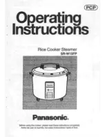
SR-W15FP
Brand: Panasonic Pages: 16
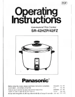
SR-42HZP
Brand: Panasonic Pages: 14
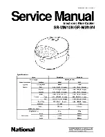
SR-MM10N
Brand: National Pages: 26

JEI0430ADS0
Brand: Jenn-Air Pages: 4

Dual Fuel Cooktop
Brand: Jenn-Air Pages: 6

RADIANT COOKTOP CVE3401
Brand: Jenn-Air Pages: 8

Toledo 110 Dual Fuel
Brand: Rangemaster Pages: 32

VG 264 220 CA
Brand: Gaggenau Pages: 15

CP240B
Brand: Jenn-Air Pages: 21

RNB8200G
Brand: Waldorf Pages: 31

33366
Brand: Hamilton Beach Pages: 28

HAP5200 532 Series
Brand: Rangemaster Pages: 32

VGRT24
Brand: Viking Pages: 13

IH30BF
Brand: GASLAND Pages: 36

CE32XK
Brand: Candy Pages: 145

Rice & Steam
Brand: HAEGER Pages: 28

SLO400 Series
Brand: Black & Decker Pages: 24

W906MFE Series
Brand: Bertazzoni Pages: 20


