Raisecom RCMS2504-240, User Manual
The Raisecom RCMS2504-240 User Manual is available for free download on our website. This comprehensive manual provides detailed instructions for setting up and utilizing the product effectively. Download your free copy from manualshive.com and get started with your RCMS2504-240 today.
Share
Download


Reviews:
No comments
Related manuals for RCMS2504-240

FHOM-103
Brand: FS Pages: 12

HI 9829
Brand: Hanna Instruments Pages: 99

INIA011
Brand: Velleman Pages: 28

PASAR 223
Brand: Acer Pages: 12

HT65
Brand: HT Pages: 24

DT-102
Brand: CEM Pages: 2

9915
Brand: CEM Pages: 22

1760/A
Brand: Beta Pages: 80

AM5
Brand: MARTINDALE Pages: 2

AM51
Brand: 3B SCIENTIFIC PHYSICS Pages: 6

Nieaf-Smitt NI 74
Brand: Wabtec Pages: 60

MS8240B
Brand: Mastech Pages: 12

YT-73084
Brand: YATO Pages: 52

MULTISCAN P2
Brand: Hanatech Pages: 116

MT832
Brand: Major tech Pages: 12
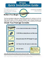
DAS-3216
Brand: D-Link Pages: 7

RS485
Brand: Tomura Pages: 2

ST-9933
Brand: REED Pages: 32


