Raisecom RC801-30B-FV35-M, User Manual
The Raisecom RC801-30B-FV35-M is a cutting-edge networking device that offers exceptional performance and reliability. Enhance your connectivity with this advanced product, and to make the most of its features, be sure to download the free User Manual from our website. It's your ultimate guide to setting up and optimizing this remarkable product.
Share
Download


Reviews:
No comments
Related manuals for RC801-30B-FV35-M
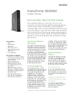
HomePortal 3801HGV
Brand: 2Wire Pages: 2

DCM202 - Express Ethernetwork DOCSIS 2.0 Cable...
Brand: D-Link Pages: 33

UCW232C
Brand: U.S. Converters Pages: 33

NB100
Brand: NetComm Pages: 1

ME31-XXXA0006
Brand: Ebyte Pages: 27

NetLink 1082/144/I
Brand: Patton electronics Pages: 28

TMX 10031161
Brand: 3Com Pages: 56

30342
Brand: InfinitiKloud Pages: 2

Merlin for GPRS G201
Brand: Novatel Pages: 54

U140E116-02
Brand: Bay Technical Associates Pages: 27

Handbook
Brand: Palm Pages: 20

Enabler II-E
Brand: Enfora Pages: 18

E95-DTU433L 485-V8 Series
Brand: Ebyte Pages: 19

FRITZ!Box 6660 Cable
Brand: Fritz! Pages: 281

Cerberus P 6331-42
Brand: Pentagram Pages: 60

3COMIMPACT IQ
Brand: 3Com Pages: 160

T-336C Series
Brand: Tainet Pages: 106

NetBridge
Brand: Accelerated Pages: 2


