Raisecom P100R001, Hardware Description
Product Description: The Raisecom P100R001 user manual is your comprehensive guide to unlocking the full potential of this exceptional product. Download it for free from our website and gain in-depth knowledge about the features, functions, and operation of the P100R001, ensuring a seamless user experience.
Share
Download


Reviews:
No comments
Related manuals for P100R001

1260 VXI
Brand: Racal Instruments Pages: 63

FINEST 716
Brand: FINE INSTRUMENTS CORPORATION Pages: 24

DVM645BI
Brand: Velleman Pages: 26

BM117
Brand: CABAC Pages: 13

RC801
Brand: Raisecom Pages: 18

BENNING MM P3
Brand: PEWA Pages: 156

airFiber NxN
Brand: Ubiquiti Pages: 20

MT-1509
Brand: Pro's Kit Pages: 24

22-812A
Brand: Radio Shack Pages: 24

RC3000 PCM
Brand: Raisecom Pages: 86

PDM 300 C3
Brand: Parkside Pages: 120

HOTWIRE 8610 DSLAM
Brand: Paradyne Pages: 56

195
Brand: Keithley Pages: 123
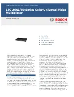
LTC 2662 Series
Brand: Bosch Pages: 3

33XR
Brand: Meterman Pages: 20

PC5000a
Brand: Sanwa Pages: 45
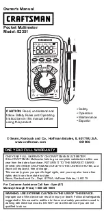
82351
Brand: Craftsman Pages: 6

UT531
Brand: UNI-T Pages: 32


