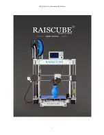
background image

USER MANUAL --Raiscube A8R 3D Printer

1

Summary of Contents for A8R

Page 1: ...USER MANUAL Raiscube A8R 3D Printer 1 ...

Page 2: ... shall not be liable to you for any damages whatsoever be they direct economic commercial special consequential incidental exemplary or indirect damages even if Raiscube has been advised of the possibility of such damages including without limitation loss of business revenue or earnings lost data or lost profits Raiscube assumes no responsibility nor will be liable for any damages to or any viruse...

Page 3: ...n radiate radio frequency energy and if not installed and used in accordance with the instructions may cause harmful interference to radio communications However there is no guarantee that interference will not occur in a particular installation If this equipment does cause harmful interference to radio or television reception which can be determined by turning the equipment off and on the user is...

Page 4: ...at source flames fireworks candles light bulbs etc ABS will catch fire and burn a thick black smoke Warning Always have adult supervision when children are present Please keep all small printed parts away from young children choking hazards There are several safety issues small tools sharp tools and HOT objects and most parts used in connection with the 3D Printer Tie back long hair and loose clot...

Page 5: ...ut of box Please refer to its packing list for all parts and check all if any damage exists especially the wires and their connectors And Switch PSU to the correct position according to the voltage in your country E g 110V for US 220V for UK STEP ONE FRAME BUILD Build Aluminum frame first and add remains to it in next three steps First step We need left frame module right frame module Z Axis Stepp...

Page 6: ... 1 Connect Z Axis Stepper R L middle bottom plate please differentiate Left stepper from right stepper by the sideway hole as in Fig b02 and we will get as in Fig b03 Here we we need 4 pcs of M3 10 Socket Cap Screws 2pcs each side Fig b02 Fig b03 ...

Page 7: ...ig b05 Fig b04 Fig b05 STEP 1 3 Pick out Back Plate Y Axis Stepper and 2pcs of M3 10 Socket Cap Screws let Y Axis Stepper join Back Plate using the screws Please refer to Fig b06 and Fig b07 for this substep Fig b06 Fig b07 STEP 1 4 Add what done in step 1 3 to the main frame which was done in step 1 2 and fasten them by 4pcs of M3 10 socket cap screws From Fig b08 to Fig b09 it illustrates how is...

Page 8: ...the right way as in pictures Afterwards time to move to next major step Build Platform assembly Fig b10 Fig b11 STEP TWO Build Platform assembly Build Platform is a function module including hotbed and its H support plate 2pcs of 420mm threaded rods 2pcs of 390mm rods front plate a belt and 12pcs M8 nuts 12sets of M8 Nut Spacer washer to install these we need 2pcs of M8 wrench and 2pcs of zip tie ...

Page 9: ... And hotbed on the top for third layer These three layers are combined together to form a movable Build Platform In brief what got to do is to turn Fig b13 into Fig b14 Fig b13 Fig b14 Layer by layer simply we divide STEP TWO into four substeps well why not three we need to connect double Z threaded rods to both Z Steppers respectively preparation for STEP THREE STEP 2 1 Fasten 420 threaded rods t...

Page 10: ...n front plate and belt into printer frame Please see Fig b19 and get ready of these And then place H train over middle plate and bury rods heads into back plate and screw 4cm distance of M8 Nut set spacer facing front plate along 420mm threaded rods add front plate to rods and lock them with threaded rods by two more nut sets Adjust nuts on threaded rod and front plate to cover 390mm rods Insert b...

Page 11: ...ck it with M3 nut from the other side We get in Fig b22 when done here And then place hotbed over H plate springs along each screw and press down through holes against H plate lock each screw from downside with Knurl Nut Please refer to Fig b23 and Fig b24 when doing PS Heat bed power cord shall be on right to connect to controller when installed Fig b21 Fig 22 Fig b23 Fig b24 ...

Page 12: ...Connect 2pcs of 350mm threaded rods to Flexible Couple on Z steppers and tighten them by driving set screws Fig b25 to Fig b26 Please note that there shall be 1 3mm free space between motor shaft and 350 threaded rods Fig b27 Fig b25 Fig b26 Fig b27 ...

Page 13: ... 3 Right Link Block including M8 15 Set screw and its washer 1pc 4 350mm rod 2pcs 5 Top Lock plate 1 pair 6 Filament Rack 1 pair 7 M3 10 socket cap screws and hex key 8 Belt 1pc 9 Zip tie 2pcs 10 Control Panel Cable 2pcs 11 Hex Wrench 2pcs 12 Control Panel Fig b28 Fig b29 STEP 3 1 Connect Left link block extruder module and right link block one by one together by 350mm rod check if extruder module...

Page 14: ...ods which are with Z motors And then turn flexible couplings downside by Z motor to screw down X Axis Module evenly Please refer to Fig b32 and Fig b33 for this Fig b32 Fig b33 STEP 3 3 Construct its roof Please have the pair of Top Lock Plate filament rack and 8pcs of M3 10 screws and one allen key too They are as in left of Fig b34 And Fig 35 shows what will be like when done this substep ...

Page 15: ...s Y belt mount X Belt on left right block and zip tie to extruder from both sides Fig 38 B Get X end stop with its support from motherboard module and place its support on upper left rod move to the location where stop extruder moving left when nozzle on left edge of hotbed Fig b39 C Together with M8 15 set screw there are two ABS spacers too Insert into two hole on right side of right link block ...

Page 16: ...ER MANUAL Raiscube A8R 3D Printer 16 Fig b38 Fig b39 Fig b40 So far we have done the build structure of RAISCUBE A8R 3D Printer One thing remaining before printing Circuit Installation Let s go for step 4 ...

Page 17: ... wire is pre assembled thus to connect circuit need to read marks on each cord and match one with the other of same mark For example Y Axis End stop with Y Axis En stop as in Fig w01 And Fig w02 shows joints of connection between motherboard and other function modules in circuit Fig w01 Fig w02 Please also note that when connecting motherboard to power supply there are one red and one black cord p...

Page 18: ...oard that is EXP1 to EXP1 EXP2 to EXP2 Please refer to Fig w04 Fig w05 and Fig w06 for this Fig w04 Fig w05 Fig w06 For further details please see our wire connect file in SD Card in carton Wire Connection mp4 Kind Reminder To make wire path look well and enable moving well please pay attention to how the wire paths as are in Fig w07 Fig 08 Fig w07 Fig w08 ...

Page 19: ...rthwhile of spending time and patience on leveling And you will also enjoy the benefits brought by A8R printer Bed Leveling includes two points the bottom surface of link blocks shall be parallel with hotbed surface and the distances of nozzle summit to each point of bed shall be same under certain tolerance Two main steps for leveling STEP ONE Get a regular rectangle object place it on either Z s...

Page 20: ... use Z home order from LCD Screen the M6 screw will hit Z axis End stop switch by then Now we check and adjust M6 screw to make the nozzle top just touch bed or allow dragging a piece of A4 paper through Move extruder to Front Right and Z Home command from Panel control check and adjust the thumbscrew under hotbed to make he nozzle top just touch bed or allow dragging a piece of A4 paper through R...

Page 21: ...gh these steps Source file acquirement Get stl or object design files from any design software e g freecad pro E etc or we can download online In our case we download one from https www thingiverse com thing 1278865 Extract xyzCalibration_cube stl from download zip file Now we have the stl file Fig s01 Fig s01 Slicing Load it to Cura software Configure slicing parameters in Cura Fig s02 If you hav...

Page 22: ... Print save GCode to SD Card Fig s03 Fig s03 Print In 3D control panel press and turn the control button to print from SD Card Main Menu Print From SD Card xyzCalibration_cube stl choose this and printing screen on with info of current print Fig s04 Fig s04 ...

Page 23: ... point of hotbed Use a spatula enclosed in package to move the cube Fig s05 Fig s05 Evaluate print quality In our cases warping happens due to leveling issue adjust hotbed and solved A regular cube model is printed When measure its dimension it should be 20 20 20mm our print is 20 08 20 02 20 04mm Fig s06 Fig s07 Fig s06 Fig s07 ...

Page 24: ...Facebook Group https www facebook com groups 1068531466501015 Youtube Installation Demo https youtu be oJS6ODX52ng Youtube Build Video https youtu be OweEknLShZ0 Raiscube A8R Live Build https youtu be C2OinymgcIg Designed in UK US Manufactured By Shenzhen Rise Technology CO LTD ...

Reviews: