
1
3
4
2
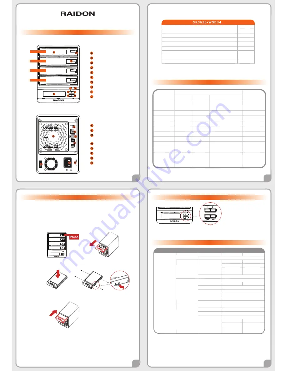
Hard drive status Indicator
Removable drive tray
Button for Tray Clamp
LCM display
UP button
DOWN button
ENTER button
ESC button
Power indicator
Alarm indicator
USB3.0 interface connection
e-SATA interface connection
FireWire 800 (1394b)
interface connection
Mute button
Power Switch
Power socket
Cooling fan
Anti-theft cord slot
GR5630-WSB3+ Quick Installation Guide
Package Contents and Product Views
Hardware Installation
Visual Status Indicator Definitions
GR5630-WSB3+
Item
Qty.
1
1
1
1
1
1
1
1
GR5630-WSB3+ (with removable drive tray enclosed)
Firewire 800 (1394b) Cable
e-SATA Cable
USB 3.0 Cable
AC Power Cable
Quick Installation Guide
Accessories Kit
CD(GUI)
Step 3 Press down the button for tray clamp to eject the removable drive tray latch and
extract the removable drive tray.
Step 1 Open the package and take out the product making sure that all the enclosed
contentsare not damaged or missing. Should you find damages or missing contents
, please contactyour supplier immediately.
Step 2 Place the system on a stable surface. Ensure that it is well ventilated without blockage
tothe vent and kept away from areas near water and damage prone areas.
Step 5 When the hard drive installation has been completed, insert the hard drive tray into
the system horizontally and secure the latch into place.
Step 6 Connect the AC power cable to the GR5630-WSB3+, and then plug the AC power to
the wall socket. Boot-up the unit.
Step 7 Set the storage mode using the LCD and buttons on the front (please refer to section
5 for front panel and LCD information).
Step 8 Connect the cable to the PC and the GR5630-WSB3+ port.
Step 9 After boot-up, your operating system will automatically detect the storage capacity
of your hard drives. Please follow the operating system instructions to configure and
format your drives. The formatted drives can be configured for the RAID setup.
Step 4 Mount your hard drives onto the removable drive tray and secure it with the screws
included in the accessory kit to avoid any damage to the hard drive due to accidental
movements.
States
Power on
Blue
Blue
Blue
Blue
Blue
Blue
Blue
Blue
Blue
Blue
Blue flash => Blue
--------
Red
Red
Blue
Blue flash
Blue flash
Blue
Blue
Source: Blue flash
Target: Blue and Purple
light on alternatively
------
------
------
------
------
------
------
Red
Red
------
1 long when
booting finished
------
------
4 short
------
------
------
4 short
4 short
------
No disk
Disk Fail
RAID Fail
Disk Idle
Format
Access
Fan Fail
Over Temp.
Rebuilding
buzzer
Power LED
Alarm LED
HDD LED
Front LED
Open the package and you should find the following :
Please make sure that the contents listed above are not damaged or missing. If you should
finddamages or missing contents, please contact your supplier immediately.
Front view
Rear view
Enter
Esc
Drive position(1)
Drive position(2)
Drive position(3)
Drive position(4)
USB3.0
Alarm Mute
Thank you for choosing product from
RAIDON Technology Inc.
This i n fo rma ti o n i n th e ma n u a l
h a s b e e n th o ro u g h l y ch e cke d b e fo re p u b l i ca ti o n , b u t ma y n o t co n fo rm to th e p ro d u ct
a ctu a l l y d e l i ve re d w h i ch me a n a ctu a l p ro d u ct sp e ci fi ca ti o n s d e p e n d o n th e p ro d u ct
sh i p p e d to yo u . An y u p d a te i n th e sp e ci fi ca ti o n s o r p ro d u ct-re l a te d i n fo rma ti o n sh a l l n o t
b e su b j e ct to fu rth e r n o ti ce b u t fo r th e l a te st i n fo rma ti o n o n th e p ro d u ct, p l e a se vi si t th e
w e b si te a s
www.RAIDON.com.tw
or contact us at
, and we wi l l g e t
b a ck to yo u a s so o n a s p o ssi b l e .
C o p yri g h t ©
RAIDON TECHNOLOGY, INC.
All rights reserved.
Description of Front Panel Operation
Enter: Enter to next level or Confirm
Esc: Back to next level or Cancel
Up / Down: Select Items
Users can set the RAID mode using the LCD and buttons on the front. The default is JBOD mode. Using
“Quick Setup” function, users can change the RAID mode to RAID 0 or RAID 5 quickly.
Please refer to LCD Information as below for other setting.
LCD Information
External 4BAY
HARDWARE
RAID
Quick Setup
Delete All RAID
Identify Disk
Show Disk Info
Identify RAID
Create RAID
Delete RAID
RAID Info
Change RAID Pwd
Rebuilding Priority
Standby Timer
System Info
Changhe Password
Logout From Menu
Alarm Control
Voltage Monitor
< 3.3V/5V/12V >
< Temp. >
< Fan Speed /
Fan Level >
Temp. Monitor
Fan Monitor
Hardware Monitor
Select Disk
< Disk Info >
Select RAID
RAID 0 / RAID 5
Select RAID
< Password >
for RAID Setup
Highest/High/Medium/Low/Lowest
< 99999min >
Firmware Version
< Password >
for System Info
< Y or N >
Mute the Buzzer
Disk 1
Disk 2
Disk 3
Disk 4
Check Disk LED
Check Disk LED
Check Disk LED
Check Disk LED
Create One RAID
RAID 0/ RAID 5
Select Disk
Disk Manager
RAID Manager
System Manager
Level 0
Level 1
Level 2
Level 3
Level 4


