Rae RAEGuard EC, User Manual
The Rae RAEGuard EC user manual provides essential instructions for safe and efficient operation. Download the manual for free from manualshive.com to learn about installation, maintenance, and troubleshooting. Ensure you have the necessary information to make the most of your Rae RAEGuard EC device.
Share
Download


Reviews:
No comments
Related manuals for RAEGuard EC

LTS
Brand: LAUREL Pages: 28

SZESKY003
Brand: esky Pages: 10

Centronic EasyControl EC415A-III
Brand: Becker Pages: 20

XE150 Series
Brand: Eddystone Broadcast Pages: 42

TA001
Brand: Retekess Pages: 2

SC202G (S)
Brand: YOKOGAWA Pages: 72

Flexiva FAX 5KW
Brand: Harris Broadcast Pages: 168

2035048
Brand: Vechline Pages: 9

Continental Electronics 802A
Brand: Varian Pages: 146

SET70R
Brand: Clas Ohlson Pages: 4

B206
Brand: STUDER REVOX Pages: 4

HR2600
Brand: PRESIDENT Pages: 21

Taylor FCC
Brand: PRESIDENT Pages: 60

AMG5713A6B9-DIN
Brand: AMG Pages: 12

k1
Brand: Ashcroft Pages: 2

GC55
Brand: Ashcroft Pages: 24

PU-1109
Brand: CYP Pages: 11
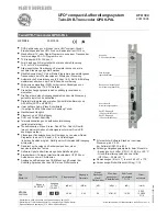
UFO 394
Brand: Kathrein Pages: 40


