background image

01 - VBOX II Front Panel

VBOX II units can be configured using the front panel buttons, which enables configuration without the need for a
computer. Configuration can also be made via the

VBOX Setup Software

.

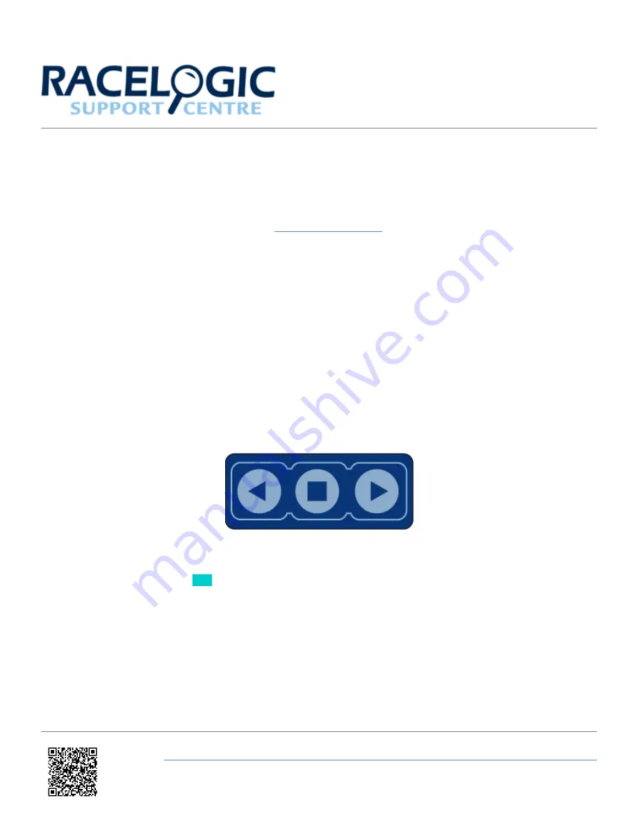
From the main screen, press the’■’ button to enter the configuration screen.

Note: Entering the configuration screen will cause the VBOX to stop logging to the SD card. When in
continuous logging mode, please ensure that the ’■' button is pushed prior to removing the SD card to avoid
data loss.

Once in the configuration screen, press the ‘◄’and ‘►’ buttons to highlight the next or previous choice in any menu, and
press ’■’ to select the highlighted option. Most Main menus contain sub-menus, for example the Settings and Setup
Antennas menus contain separate menus for each parameter.

Note:

The options highlighted in blue are only available on the SL series units.

https://racelogic.support//01VBOX_data_loggers/VBOX_II_Range/VBOX_II_User_Guide/01_-_VBOX_II_Front_Panel

1

Summary of Contents for VBOX II

Page 1: ...continuous logging mode please ensure that the button is pushed prior to removing the SD card to avoid data loss Once in the configuration screen press the and buttons to highlight the next or previo...

Page 2: ...gurations menu This menu contains separate sub menus for pitch antenna and roll antenna pairs SMOOTHING Press to edit the smoothing levels of the Lat acc and Long acc channels and also Slip Pitch Roll...

Page 3: ...en the following modes VCI MODE To connect any external CAN modules to the input of the VBOX II RACELOGIC MODULES MODE To connect Racelogic CAN modules to the RLVBOX II input or output LOG OPTIONS Pre...

Page 4: ...BACK Press to go back to the Main menu https racelogic support 01VBOX_data_loggers VBOX_II_Range VBOX_II_User_Guide 01_ _VBOX_II_Front_Panel 4...

Page 5: ...10 degrees SWAP ANTENNAS Set to ON to allow the primary Antenna A to be mounted ahead of the Secondary Antenna B Default is OFF Then press to confirm SLIP OFFSET Press to enter the Slip offset sub men...

Page 6: ...buttons to enable or disable the LEVEL option With the LEVEL set to YES the RTK lock is more resilient But maximum ROLL or PITCH in this mode should be 10 degrees ROLL OFFSET Press to enter the Roll...

Page 7: ...d then use the and buttons to change the amount of smoothing applied to the Slip angle channel Then press to confirm 0 0 5 0 0 1 steps PITCH Press and then use the and buttons to change the amount of...

Page 8: ...t the maximum Speed Then press to confirm 0 400 km h 1 km h steps MAX VALUE Only available when output is set to LAT ACC LONG ACC PITCH SLIP or ROLL Press and then use the and buttons to set the maxim...

Page 9: ...s to set a test value that the Digital output will simulate Then press to quit EXIT Press to exit the setup menu and cause the settings to be saved in EEPROM https racelogic support 01VBOX_data_logger...

Page 10: ...g 0 1g steps LAT ACC 1 to 2 g 0 1g steps LONG ACC VALUE 0V Only available when output is set to SPEED Press and then use the and buttons to set the velocity to represent 0 V Then press to confirm 0 39...

Page 11: ...st value that the Analogue output will simulate Then press to quit EXIT Press to exit the setup menu and cause the settings to be saved in EEPROM https racelogic support 01VBOX_data_loggers VBOX_II_Ra...

Page 12: ...1 8 m CEP 40CM position accuracy 40CM 20CM position accuracy 20CM KALMAN FILTER Press and then the and buttons to set Kalman filter options POSITION LEVEL Smoothes the positional data VELOCITY LEVEL...

Page 13: ...eeprom message screen notifying you of the process https racelogic support 01VBOX_data_loggers VBOX_II_Range VBOX_II_User_Guide 01_ _VBOX_II_Front_Panel 13...

Reviews: