background image

4 8 6   •   4 8 2   •   8 6 3   •   6 8 2

QuickLabel.com

Part Number: 22834571-EN-E | Revision 2.0
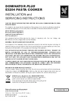
Pronto! 486


• 

Prints or laminates in

    600 dpi at up to 4 ips
Pronto! 482


 Prints or laminates in

    200 dpi at up to 10 ips

Pronto! 863


 Prints or laminates in

    300 dpi at up to 6 ips  
    on labels up to 8.5” wide
Pronto! 682


 Prints or laminates in

    200 dpi at up to 8 ips 
    on labels up to 6.5” wide

Summary of Contents for pronto! 486

Page 1: ...Pronto 486 Prints or laminates in 600 dpi at up to 4 ips Pronto 482 Prints or laminates in 200 dpi at up to 10 ips Pronto 863 Prints or laminates in 300 dpi at up to 6 ips on labels up to 8 5 wide Pro...

Page 2: ......

Page 3: ..._______________________________ QuickLabel Systems an Astro Med Inc Product Group World Headquarters 600 East Greenwich Ave West Warwick RI 02893 Tel 877 757 7978 Fax 401 822 2430 E mail info QuickLab...

Page 4: ...ted promptly to QuickLabel QuickLabel will at its option repair the printer or repair or replace its defective part s at no additional charge under our QuickSwap Repair Loaner Service If QuickLabel de...

Page 5: ...rchase for a period of 90 days or for 1 million inches of thermal transfer ribbon whichever comes first contingent upon the use of QuickLabel Systems thermal transfer ribbon QuickLabel Systems printhe...

Page 6: ...es e mail info QuickLabel de Technical Support e mail support QuickLabel de QuickLabel France Parc Euclide ZA la Clef de St Pierre 10A Rue Blaise Pascal 78990 ELANCOURT Tel 33 1 34 82 09 00 Fax 33 1 3...

Page 7: ...against harmful interference when the equipment is operated in a commercial environment The equipment generates uses and can radiate radio frequency and if not installed and used in accordance with th...

Page 8: ...65 EU and 2002 95 EU Restriction of the Use of Certain Hazardous Substances in Electrical and Electronic Equipment This declaration is based on information provided by suppliers based on reasonable i...

Page 9: ...4 108 EC I the undersigned hereby declare that the equipment specified above conforms to the above Directive and Standard Je Soussign d clare que l quipment sp cifi ci dessus est en conformit avec la...

Page 10: ...quipment specified above conforms to the above Directive and Standard Je Soussign d clare que l quipment sp cifi ci dessus est en conformit avec la directive et le stan dard ci dessus Ich der unterzei...

Page 11: ...e conforms to the above Directive and Standard Je Soussign d clare que l quipment sp cifi ci dessus est en conformit avec la directive et le stan dard ci dessus Ich der unterzeichnende erkl re hiermit...

Page 12: ......

Page 13: ...t interface 1 8 USB interface 1 10 Optional Interfaces 1 11 Switching the label printer on and off 1 12 Chapter 2 Operating panel 2 1 About the Operating Panel 2 2 Layout of the operating panel 2 3 Fu...

Page 14: ...the support bracket Pronto 863 6 2 Loading labels from a roll 6 3 Positioning the label roll on the roll retainer 6 3 Inserting a label strip into the printhead 6 4 Setting the label sensor 6 4 Windi...

Page 15: ...ice Overview 8 18 Contents of Delivery 8 19 Connecting to Power Supply 8 19 Selection of the Rewind Direction 8 20 Aligning the Guide Axle 8 21 Rewinding Directly onto the Rewind Axle 8 22 Rewinding o...

Page 16: ...erface 8 51 Explanation of the Signals 8 52 Circuit Diagram of Inputs 8 54 Circuit Diagram of Outputs 8 55 WLAN Card 8 56 Function 8 56 Mounting 8 56 Setup 8 57 External Operating Panel 8 58 Delivery...

Page 17: ...nfiguration 10 10 Loading Material 10 12 Operation 10 12 Maintenance 10 14 Error Messages 10 16 Chapter 11 Cleaning and basic maintenance 11 1 Maintenance plan 11 2 Tools and cleaning agents 11 3 Gene...

Page 18: ...FTP printer management 14 1 FTP logon 14 2 Directory structure of the FTP server 14 3 FTP firmware update 14 4 Chapter 15 Memory media 15 1 Suitable Memory Media 15 2 Installation 15 2 Formatting 15...

Page 19: ...Pronto 482 486 682 863 7 External Rewinder ER4 17 4 External Unwinder EU4 17 5 Appendix A Menu Map A 1...

Page 20: ...8 Pronto 482 486 682 863...

Page 21: ...tions and disposal information Unpacking the label printer Describes how to unpack and inspect the printer Setting up the label printer Describes how to set up the printer after unpacking Connecting t...

Page 22: ...o print suitable media which have been approved by the manufacturer Any other or additional use is not intended The manufacturer supplier is not liable for damage resulting from misuse Any misuse is a...

Page 23: ...of used devices separately from other waste i e via an appropriate collection site The modular nature of the label printer allows it to easily be disassembled into its component parts so that the part...

Page 24: ...ter for damage which may have occurred during transport 3 Check delivery for completeness Label printer Empty cardboard core mounted on ribbon take up hub Tear off plate basic devices only or Dispense...

Page 25: ...ce and the print media can be damaged by moisture and water The label printer may only be set up in a dry place protected from sprayed water Set up printer on a level surface Open cover 1 of the label...

Page 26: ...n jack 6 2 Insert plug of the power cable into a grounded electrical outlet 1 Serial RS 232 interface 2 USB 2 0 high speed slave interface 3 Two USB master interfaces for keyboard scanner optional int...

Page 27: ...S 422 485 to a USB master interface Connection to a wireless network via optional WLAN card installed in the slot for type II PC card 1 Serial RS 232 interface 2 USB 2 0 high speed slave interface 3 T...

Page 28: ...f problems occur contact the computer manufacturer for interface assignments and note the pin assignments below Ethernet interface To connect the label printer to a network jack you will require a pat...

Page 29: ...e below Print services Raw IP and LPD in MS Windows The print services Raw IP and LPD are not available in all operating systems In general special tools are required to set up print services Informat...

Page 30: ...icon of the label printer A pop up menu appears 3 Select Properties in the pop up menu 4 Open the Details or Connections tab This tab contains among other things the connections which were also set up...

Page 31: ...the printer the following optional interfaces are available Parallel Centronics RS 422 485 WLAN card 802 11b g The Parallel Centronics interface and the RS422 485 interface must be connected at a USB...

Page 32: ...ctions have been made 1 Switch printer on via the power switch 1 The printer runs through a system test and then indicates the system status Ready in the display If an error has occurred while the sys...

Page 33: ...2 Operating panel This chapter contains the following sections About the Operating Panel Provides an overview of the operating panel Functions of the operating panel during printing Describes operati...

Page 34: ...rint speed configuration of the ports language and time see Chapter 5 Configuration start test functions see Chapter 5 Configuration and Chapter 12 Test functions control standalone operation with mem...

Page 35: ...y 1 and the navigator pad 2 with five integrated buttons The graphical display informs you of the current status of the printer and the print job reports errors and shows the printer settings in the m...

Page 36: ...line of the screen depending on the configuration of the printer They inform you of the current status of the printer at a glance For configuration of the status line see Status line on page 5 10 Symb...

Page 37: ...s ready and can receive data The display shows the text Ready and the configured symbol indicators such as the time and date Input buffer Access to memory card Printer receiving data Button Label Func...

Page 38: ...symbol Fault correctable mode An error which can be remedied by the operator without canceling the print job has occurred The print job can be continued once the error is remedied Button Label Functi...

Page 39: ...up the display shows the error type and following symbol Button Label Function pause flashes continue print job after error recovery printer switches to Printing Label mode cancel illuminates press b...

Page 40: ...2 8 Operating panel Switch off printer via the power switch and switch it on again or Push the cancel button If the error occurs repeatedly notify Support...

Page 41: ...Pronto 482 486 682 863 3 1 Chapter 3 Offline menu This chapter contains the following sections Offline menu Describes the structure and navigation of the offline menu...

Page 42: ...tatus functions the set parameters can be displayed or printed 1st menu level 2nd menu level Access Memory card Label from card Only with memory medium inserted in the default card slot Print director...

Page 43: ...Pronto 482 486 682 863 3 3 Test Status print Font list Device list WiFi status Only with WLAN card installed ASCII Dump Mode Test grid Label profile 1st menu level 2nd menu level Access...

Page 44: ...3 4 Offline menu Setup Local settings PIN protection possible Machine param Print param Interfaces Status line Security 1st menu level 2nd menu level Access...

Page 45: ...mory medium inserted in the default card slot PIN protection possible Save settings Only with memory medium inserted in the default card slot PIN protection possible Load settings Only with memory med...

Page 46: ...u option to the left Scrolls to the left Cursor shift to the left Menu option to the right Scrolls to the right Cursor shift to the right Start of a selected menu option Confirmation of the selected v...

Page 47: ...86 682 863 4 1 Chapter 4 Device types This chapter contains the following sections Standard device Describes the standard device version Peel off device version Describes the peel off device version w...

Page 48: ...off automatically with the cutter accessory For details see Chapter 9 CU4 Cutter Accessory The labels can be wound up with the external rewinder accessory For details see External Rewinder ER1 on page...

Page 49: ...stalling the tear off plate see Removing and installing the rewind guide plate dispense plate or tear off plate as with the standard device In Peel Off mode the label is peeled off the liner after pri...

Page 50: ...4 4 Device types...

Page 51: ...is chapter contains the following sections Configuration via the operating panel Describes how to change printer settings using the operating panel Configuration via the printer website Describes how...

Page 52: ...al settings Parameter Meaning Default Country Setting the display language and the country specific date and time formats You can also overwrite the time formats via software The changes are not saved...

Page 53: ...format set via the Country parameter You can also change the time via software The change is not saved permanently however Parameter Meaning Default Printhead pos X Shifting of the entire print image...

Page 54: ...e param menu and the software are added together 0 0 mm Tear off pos Shifting of the tear off position in the direction of paper flow With positive values the label strip is transported farther out of...

Page 55: ...alue is then especially necessary if the printing intensity has changed after replacing the printhead To adapt the printing intensity when using different media print speeds or printing contents you s...

Page 56: ...ncy between the label and label gap Bottom Reflect Detection using reflex marks on the bottom of the medium Continuos media Synchronization of the paper flow when using endless media in cutting mode M...

Page 57: ...printed when the error occurs is repeated Off Print job is continued with the next label On Pause reprint Printing of another label with the information of the previous print job by pressing the pause...

Page 58: ...default card slot CompactFlash or PC Card card slots on the back of the printer Ext CompactFlash card slot in the external operating panel USB Memory USB fl ash drive at USB master interface IFFS Inte...

Page 59: ...the optional WLAN card If interface is not installed this option is not available Ethernet Configuration parameters of the Ethernet interface card You can access additional configuration parameters f...

Page 60: ...on the network through which the connection can be established is used for this The address of the router can also be issued via DHCP Off Network error Printer switches to Error mode when problems wit...

Page 61: ...0 Date time digital Digital display of current date and time Off 31 Ribbon supply Displays the current ribbon supply in the form of a horizontal bar Off 16 Wi Fi signal strength Displays the current s...

Page 62: ...ty Security menu 3 Select the value On with the left and right arrow buttons User space Content of the user memory in the clock circuit max 31 byte Off 22 Used memory Displays the current memory used...

Page 63: ...nu button 2 Select Setup Security PIN menu 3 Select the digit of the PIN to be changed with the left and right arrow buttons 4 Assign the selected digit a number with the up and down arrow buttons 5 R...

Page 64: ...dy is displayed Description of the printer website The printer website contains the following tabs Status general status description See Status tab on page 5 15 Setup configuration parameter settings...

Page 65: ...nter Number of labels printed since commissioning Previously printed paper length with thermal transfer printing Previously printed paper length with thermal direct printing Printer status Ready Print...

Page 66: ...hows the current printer display You can set the update interval on the scale below the display The display is not updated automatically with the 0 setting Reset Hard functions like switch off and swi...

Page 67: ...of the tab The tree structure can be expanded in different ways Click circular symbol in front of the menu symbol once The corresponding menu is expanded Double click menu symbol or menu name The corr...

Page 68: ...sent to selected addresses when certain status and error messages are generated To activate Set parameter to On Enter IP address of the SMTP server Enter a valid e mail address for the printer in the...

Page 69: ...IP address of the management station s receiver 1 or receiver 2 Assign the Community parameter the value public Off Time server Synchronization of the date and time of the printer To activate Set par...

Page 70: ...on An entry for a higher order description e g note is automatically accepted for all subordinate descriptions e g Start Not ready Ribbon running out SNMP 1 SNMP 2 Management stations on local network...

Page 71: ...d Widget may only be added if another widget is deleted black Widget is already activated E mail Valid e mail address for the SMTP server to which the message is to be sent Click cell and enter e mail...

Page 72: ...f the display e g 128 pixels are displayed in the Display usage field Removing a status parameter 1 Select parameter in the list 2 Click Remove Fonts tab The most important parameters of the fonts ava...

Page 73: ...ices tab provides an overview of the most important hardware components installed in the printer and the optional devices connected The contents of the display correspond with those of the Device list...

Page 74: ...5 24 Configuration...

Page 75: ...oading transfer ribbon Describes how to load transfer ribbon Setting the feed path of the transfer ribbon Describes how to reduce ribbon wrinkling by adjusting the feed path Removing and installing th...

Page 76: ...Closing the Support Bracket 1 Turn lever 2 counterclockwise until it stops 2 Close the support bracket 1 Ensure that the all pins 3 are captured by the drillings of the support bracket 3 Turn lever 2...

Page 77: ...the roll retainer in such a way that the labels can be inserted into the printhead in the right position The printing side of the labels must be visible from above 5 Re mount the margin stop 1 onto th...

Page 78: ...6 against the outer edge of the label strip Setting the label sensor The label sensor 2 can be shifted perpendicular to the direction of paper flow for adaptation to the label medium The sensor unit...

Page 79: ...mode the labels are wound up internally after printing for later use 1 Remove the locking system for Rewind mode if necessary see Removing and installing the locking system on page 6 13 and install re...

Page 80: ...The label roll is loaded for use in Rewind mode Winding up the liner in Peel Off mode In Peel Off mode the labels are removed after printing and only the liner is wound up internally 1 Lift the pinch...

Page 81: ...oaded for use in Peel Off mode Setting the head locking system The printhead is pushed on via two plungers on Pronto 863 three plungers The location of the outer plunger must be set to the width of th...

Page 82: ...counterclockwise to lift the printhead 2 Cut label strip and wind it fully around the rewinder 3 3 Hold rewinder 3 firmly and turn knob 2 clockwise The rewinder spindle relaxes and the wound roll 4 i...

Page 83: ...oll retainer 3 5 Move the margin stop 1 against the media strip until chassis 5 and margin stop 1 touch the media strip without clamping or bending it 6 Turn ring 2 clockwise so that the arrow points...

Page 84: ...y hub 4 counterclockwise until the transfer ribbon roll is secured 5 Slide suitable transfer ribbon core 1 onto the transfer ribbon take up hub 2 and secure it in the same way 6 Guide transfer ribbon...

Page 85: ...prevent wrinkles See also Setting the head locking system on page 6 7 The adjustment is best carried out during printing 1 Read current setting on the scale 1 and record if necessary 2 Turn screw 2 w...

Page 86: ...rsions with a locking system on the rewind assist roller the locking system on the rewind assist roller must be removed see Removing and installing the locking system on page 6 13 for operation in Rew...

Page 87: ...nd remove them 3 Remove the pinch roller 4 and bottom plate 3 Installing the locking system 1 Position printer at edge of table so that the oblong hole is accessible from below 2 Place the pinch rolle...

Page 88: ...6 14 Loading media...

Page 89: ...de Describes peel off mode Internal rewinding Describes rewinding labels Caution The printhead can be damaged if handled improperly Do not touch the bottom of the printhead with your fingers or sharp...

Page 90: ...ontinuous media are printed After printing the label strip is separated by hand The label printer is equipped with a tear off plate for this Optionally the label can be cut off or label strips can be...

Page 91: ...winder External Rewinder ER4 Describes how to use the ER4 external rewinder External Unwinder EU4 Describes how to use the EU4 external unwinder Label Present Sensor PS6 Describes how to use the PS6 l...

Page 92: ...mpatible USB keyboard which supports code set 3 to the printer Insert connection cable of the keyboard into the USB master interface on the back of the printer Special key functions General Key Functi...

Page 93: ...lt key Additional special characters can be output using a sequence of two characters whereby you must press the Alt key when entering the second character Some special characters cannot be shown in t...

Page 94: ...tered by first entering the corresponding character in the Z1 column and then entering the character in the Z2 column while pressing the Alt button GR Deutschland FR France US USA SG Schweiz SF Suisse...

Page 95: ...ing the character 1st entry 2 entry Alt n ZZ Z1 Z2 A A A A A A A E C C D D E E E E I I I I I J L N ZZ Z1 Z2 O O O O O O O E R S U U U U Y Y Z a a a a a ZZ Z1 Z2 a a e _ a c c c d e e e e e i i i i i j...

Page 96: ...rewinder runs for a maximum of one more second Safety Instructions Delivery Contents 1 Rewinder Note This accessory is compatible only with the Pronto 482 and 486 models Caution The printer must be s...

Page 97: ...Pronto 482 486 682 863 8 7 2 Flange 3 Clamp 4 Rewind Axle Adapters 2...

Page 98: ...to install the rewinder the front cover has to be removed 1 Loosen the screw 7 2 Remove the front cover 6 The External Rewinder is mounted on the printer so it is not necessary to adjust the device Ca...

Page 99: ...e printer 4 Secure the rewinder by tightening the spindle 8 Selection of the Rewind Method It is possible to rewind inside and outside wound labels with the rewinder But before rewinding the method ha...

Page 100: ...8 10 Accessories Rewinding directly onto the Rewind Axle...

Page 101: ...l strip with the clamp set in the groove of the rewind axle 15 Consider the required method of rewinding The broken line is valid for inside wound labels The full line is valid for outside wound label...

Page 102: ...8 12 Accessories Rewinding onto 3 in 76 mm Cardboard Core...

Page 103: ...than the width of the cardboard core Tighten the knurled screw 19 5 Slide the cardboard core 20 over the two adapters 4 until it is touching the disc 14 6 Feed the label strip over the guide bar 16 an...

Page 104: ...8 14 Accessories Rewinding onto 1 56 in 40 mm Cardboard Core Note For rewind mode the spring on the rewind axle must be mounted...

Page 105: ...ardboard core Consider the required method of rewinding The broken line is valid for inside wound labels The full line is valid for outside wound labels 5 Slide the flange 2 onto the rewind axle 15 un...

Page 106: ...e liable for damage resulting from unauthorized use the user shall bear the risk alone Usage for the intended purpose also includes complying with the operating manual including the manufacturer s mai...

Page 107: ...residual waste Send the parts for recycling Function The External Rewinders are peripheral devices for transfer printers of different manufacturers During processing of large print jobs it is possible...

Page 108: ...8 18 Accessories Device Overview ER4 1 Switch Rotating Direction 2 Rewind Axle 3 Roll 4 Guide Axle 5 Rewind Adapter 6 Flange 7 Clamp 8 Power Switch 9 Power Input Module...

Page 109: ...voltage of 230V 50 Hz and with a voltage of 115V 60 Hz without making changes to the printer The rewinder is ready for use if the power cable 3 supplied in the accessories is inserted into a power su...

Page 110: ...Direction The selection of the rewind direction is depend of using an inside or outside wound label Turn off the rewinder and set the switch 1 to the required direction of rewinding Rewinding with lab...

Page 111: ...r the guide axle should be aligned so that the label strip is led horizontally from the printer to the rewinder 1 Loosen the guide axle 1 by turning it counterclockwise 2 Move it in the guide plate 2...

Page 112: ...e the spring 2 from the rewind axle Warning Risk of injury by rotating engine parts When switching on the Rewinder starts immediately and winds to the material is tightened Note Consider the required...

Page 113: ...lamp 5 over the label strip with the clamp set in the groove of the rewind axle 7 4 Slide the clamp 5 as far as possible towards the disc 6 5 Slide the flange on ER4 4 onto the rewind axle so that it...

Page 114: ...at the spring 1 is mounted on the rewind axle 2 Consider that the cardboard core 3 should be about 1 mm 0 04 in broader than the label strip Warning Risk of injury by rotating engine parts When switch...

Page 115: ...lange 5 with the knurled screw outward onto the rewind axle until it stops 5 Tighten the knurled screw 4 on the flange 6 Switch on the rewinder on the power switch Note Consider the required direction...

Page 116: ...remove the spring from the rewind axle Consider that the cardboard core 3 should be about 1 mm 0 04 in broader than the label strip Warning Risk of injury by rotating engine parts When switching on th...

Page 117: ...cardboard core Tighten the knurled screw 2 3 Put the cardboard core 5 on the rewind axle 2 4 Feed the label strip over the guide axle 9 and under the roller 8 up to the cardboard core 5 5 Affix the e...

Page 118: ...fety Instructions Delivery Contents 1 Unwinder 2 Winding Axle Note This accessory is compatible only with the Pronto 482 and 486 models Caution During operation the rotating rewinder axle with the fla...

Page 119: ...ters 2 5 Screws 8 Placing the Unwinder When you switch between outside and inside wound materials you have to turn the unwinder 180 degrees Compare the position of the swing arm 7 in the two following...

Page 120: ...Preparing the Winding Axle and the Flanges There is a spring 8 mounted on the winding axle 2 to guarantee proper stability of the unwinding material when using rolls with a 1 56 in 40 mm cardboard cor...

Page 121: ...e winding axle Note Before mounting the winding axle read this section and Insertion of the Prepared Winding Axle on page 8 34 Pay attention to the running of the media in dependence to inside and out...

Page 122: ...t touches the flange slightly Push the second flange 3b with the attachment outside onto the axle until it touches the material roll Tighten the knurled screw 13 in the flange 3b Now you can continue...

Page 123: ...ent outside onto the axle until it touches the material roll The cardboard core of the material roll has to be positioned on the winding adapters Tighten the knurled screw 13 in the flange 3b Now you...

Page 124: ...he axle with material in the unwinder When hanging up the flange with the knurled screw has to be in front Feed the label strip 14 over the swing arm 7 and the rewind axle 15 to the printer Note Pay a...

Page 125: ...r on page 8 35 Adjusting the Unwinder To avoid crinkling in the material the unwinder has to be aligned exactly to the printer The printer is correctly aligned when the running of the material at the...

Page 126: ...gnal is sent to the printer indicating that the label has been removed from the peel position the printer will begin printing the next label of the print job The integrated present sensor registers re...

Page 127: ...r Label is removed Once a present sensor is mounted on the printer and is ready for operation the printer can be used in dispense mode The print of a label is executed if A print job is available Ther...

Page 128: ...an External Control In this operation mode an external control is connected to the peripheral interface of the Present Sensor PS6 After removing the label printing of the next label will be executed b...

Page 129: ...e is inserted into the 15 pin peripheral port 5 of the printer Caution The printer must be powered off before attaching the module The module may only be used for the purposes described in this manual...

Page 130: ...l on the dispense plate Peel position with the Note The power supply of the module is made by the peripheral port of the printer Connecting an external voltage at the modules peripheral interface coul...

Page 131: ...n a position where the leading edge of the following label has already been forwarded beyond the printhead The printer then will backfeed the label material from its peel position to the printhead The...

Page 132: ...Start signal 2 XFEH Input External Error 3 4 XESP Output Label in peel position Control bit 3 5 XEDG Output No existing print job Control bit 1 6 XDNB Output Printer is not ready Control bit 2 7 XEDST...

Page 133: ...ble to press the PAUSE key to continue the print job Printing of the next label starts when the signal XSTART is active If the external error occurred while the printer was printing the label will be...

Page 134: ...xternal error occurred while the printer was printing the label will be printed again A label which was in peel position while the external error occurred will not be printed again In that case the si...

Page 135: ...tage of 24V in the input circuit For each signal X IN there is a separate reverse line X IN R via the plug connector From that the following matching pairs of signals result The external control devic...

Page 136: ...line R L and the respective output Examples External Circuits to operate Present Sensor PS6 The external control device trigger switch external control optical sensor must be equipped with a 15 pin S...

Page 137: ...Pronto 482 486 682 863 8 47...

Page 138: ...an forward the media immediately after printing to an external device like a loop control Connection is made between the Pause Adapter and the printer using the peripheral connector on the printer The...

Page 139: ...PS7 1 Loosen the screw 2 2 Remove the front cover 1 Caution The printer must be powered off before attaching the Pause Adapter The Pause Adapter may only be used for the purposes described in this ma...

Page 140: ...e Pause Adapter 3 by tighten the screw 2 Modes of Operation The printer is ready for operation if all connections have been made and all materials are loaded correctly Answers about loading the materi...

Page 141: ...een PIN1 XPSE and PIN9 RXPSE The print job is executed if a print job is available between XPSE and RXPSE is low level signal pause inactive between XFEH and RXFEH is low level signal there is no exte...

Page 142: ...tion 1 XPSE Input Pause signal 2 XFEH Input External error 3 Do not use 4 Do not use 5 XEDG Output No existing print job 6 XDNB Output Printer is not ready 7 XEDST Output Print of a label has started...

Page 143: ...rently available In this state the contact between PIN5 and PIN14 is opened XDNB Printer is not ready An error has occurred on the printer The label print is stopped and the details and type of error...

Page 144: ...ving an external voltage Circuit Diagram of Inputs The XPSE and XFEH inputs are optocouplers with a current limiting resistor of 2 2kW giving a voltage of 24V in the input circuit For each signal X IN...

Page 145: ...am of Outputs All outputs are recognized through solid state relays Their outputs are connected to one another on one side The joint line is lead to the plug connector as a R L signal The switch funct...

Page 146: ...upported Mounting Slide the WLAN card 1 considering the correct orientation of the two rail guide 3 into the PC Card slot 2 until it stops Note When using the WLAN card the printer port for the wired...

Page 147: ...ion To check the reception conditions at the installation location of the printer in the menu Setup Status line the widget Wi Fi signal strength can be activated So the signal strength will be shown i...

Page 148: ...d a scanner or an USB flash drive If both panels are connected to the printer you can use both with the same priority The displays show the same 1 Slot for CompactFlash memory card 2 Display 3 USB mas...

Page 149: ...are in millimeters Fix the external operating panel with 2 screws DIN7984 M4x10 Dimensions are in millimeters Connect the delivered cable at the 9 pin SUB D plug of the panel and at one of the USB int...

Page 150: ...cl washer 2 from the rear side into the drilling 1 Note This accessory is compatible only with the Pronto 482 and 486 models Danger Risk of death via electric shock Before opening the housing cover di...

Page 151: ...gated hole onto the thread of screw 3 6 Fix the antistatic brush in the upper elongated hole with the screw 6 at the drilling 4 Adjustment 1 Load label material 2 Loosen the screw 6 3 Move the antista...

Page 152: ...8 62 Accessories...

Page 153: ...unting the Cutter Describes how to mount the cutter Printer Configuration Describes printer configuration options Media Loading References media loading information Operation Describes how to operate...

Page 154: ...ents then automatically backfeed the label so that after making a cut the label roll will be repositioned and ready for printing the next label An optional Cutter Tray is available Perf Cutter The Per...

Page 155: ...ng the cutter Risk of injury particularly during maintenance the cutter blades are sharp The cutter may only be used when it is mounted on the printer Do not try to cut any materials which exceed the...

Page 156: ...or a dispense plate on the printer to lead the material through the blades of the cutter The printers have such a plate mounted when delivered 1 To dismount the rewind guide plate loosen the screws 2...

Page 157: ...1 Loosen the screws 1 2 Place the cutter tray 2 on the screws 1 in front of the tear off plate or the dispense plate and slide it to the left until it stops 3 Tighten the screws 1 4 The length of the...

Page 158: ...2 Loosen the screw 2 3 Remove the front cover 1 4 Insert the pins 3 of the cutter 7 into the holes 4 of the printer 5 Press the cutter against the printer That way the plug of the cutter will be conne...

Page 159: ...media will be advanced before it is cut that means the distance between the cut edge and the rear edge of the label increases The setting should be made when first operating the printer and cutter or...

Page 160: ...is set to smart the backfeed will only be performed if the front label is in its cut position and the printer has not yet received all of the data for printing the following label Otherwise the print...

Page 161: ...s Once the cutter is mounted on the printer and is ready for operation the printer can be used in cut mode All labels in a print job will be printed without stopping and be cut as chosen in the softwa...

Page 162: ...lade 2 must be greased regularly We recommend for lubrication an All round High quality Grease Hold a greased brush on the cylindrical area and turn the axle 3 with a screwdriver for slotted head scre...

Page 163: ...er from the printer 2 For cleaning the drive roller open the print head and remove the media from the printer 3 For cleaning the circular blade you can turn the axle 3 with a screwdriver for slotted h...

Page 164: ...late 15 and the linear blade 11 4 Unscrew the screws 8 and remove the bearing plate 15 sideways 5 Take the circular blade 2 out of its bearing 5 Now you can slacken the spring 6 of the linear blade Ca...

Page 165: ...he mounting plate 9 and the linear blade 11 1 Turn the linear blade 11 backwards The spring 6 gets tense Insert the Axle of the new circular blade 2 with the washer A in the bearing 5 of the mounting...

Page 166: ...he clock wheel 2 to another 1 Unscrew the cover 4 by loosening the screws 3 5 and 9 at the rear 2 Loosen the screw 8 about 5 mm from the profile of the cutter 3 Turn the axle 7 of the circular blade w...

Page 167: ...Pronto 482 486 682 863 9 15 4 Tighten the screw 8 for arresting the circular blade Caution If you tight screw 8 too strong you could damage the screw thread...

Page 168: ...9 16 CU4 Cutter Accessory...

Page 169: ...es how to install the CS4 cutter stacker Printer Configuration Describes how to configure the printer for use with the CS4 cutter stacker Loading Material Describes how to load media Operation Describ...

Page 170: ...tter Stacker Accessory CS4 Cutter Stacker 1 Cover 2 Knurled screw 3 Table 4 Handle for height displacement of the table 5 Upper blade 6 Lower blade 7 Safety cover 8 Scale 9 Side plate movable 10 Side...

Page 171: ...the printer There is a risk of injury particularly during maintenance as the cutter blades 3 4 are sharp Operate the stacker with properly mounted safety covers 5 only Mount matching safety covers 5 w...

Page 172: ...erating manual Work going beyond this may only be performed by trained personnel or service technicians Unauthorized interference with electronic modules or their software can cause malfunctions Other...

Page 173: ...Sensor 1 Loosen screw 4 2 Remove cover 3 or present sensor Removing the locking system 1 Position printer at edge of table so that the oblong hole is accessible from below 2 Screw out screws 6 8 and...

Page 174: ...of the stacker will be connected to the peripheral port 2 of the printer 3 Secure the stacker with the screw 6 Warning Disconnect the printer from the electrical outlet before mounting or removing th...

Page 175: ...e plates 4 to the media width using the scale 1 Use the edges 3 of the side plates as pointers 3 Tighten screws 2 Warning Equip the stacker only with a table designated for the media to be used and th...

Page 176: ...oles of the retainer 4 and move the table to the printer until it stops 3 Tighten the knurled nuts 3 Mounting the Safety Cover Warning Equip the stacker only with safety covers designated for the medi...

Page 177: ...486 682 863 10 9 1 Open cover 1 2 Loosen two screws 3 in the side plates 4 6 several turns 3 Place the safety cover 2 onto the screws 3 and slide the cover to the printer 4 Tighten the screws 3 5 Clo...

Page 178: ...n relative to the printed image Cut position with the initial offset value of 0 causes cut in the middle of the gap between two labels If the cut position value is positive the media will be advanced...

Page 179: ...n using endless media in cutting mode After loading media press the feed key That way a short feed and a synchronization cut are realized Gap Sensor Backfeed Method for backfeeding the material Backfe...

Page 180: ...als are loaded correctly Move the table 2 upwards using the handle 3 until it stops Switch on the printer The cutter performs a cut Note To operate the cutter with continuous material in the printer E...

Page 181: ...l Pronto 482 486 682 863 Programmer s Guide Send a print job All labels in the job will be printed without stopping and be cut With the movement of the upper blade the labels will be pressed onto the...

Page 182: ...utter shaft with an Allen key 2 5 mm and that way displace the upper blade 3 5 Remove dust and paper particles with a soft brush or a vacuum 6 Remove all deposits at the cutter blades 3 4 with isoprop...

Page 183: ...Pronto 482 486 682 863 10 15 8 Move the table upwards until it stops 9 Close cover...

Page 184: ...ing Reduce the brake of table movement as necessary by turning the screw 1 anti clockwise in steps of quarter turns Cutter blocked Cutter cannot reach the home position within a defined time after cut...

Page 185: ...g the printhead Describes how to clean the printhead Cleaning the label sensor Describes how to clean the label sensor Replacing the printhead on Pronto 482 486 models Describes how to replace the pri...

Page 186: ...direct thermal printing each time the label roll is changed thermal transfer printing each time the transfer ribbon is changed or when the print image is adversely affected Clean label sensor see Cle...

Page 187: ...area with a soft brush or vacuum cleaner Clean outer surfaces with an all purpose cleaner Note For adjustments and simple installation work use the accompanying hexagonal wrench located in the bottom...

Page 188: ...n lever counterclockwise to lift the printhead 2 Remove labels and transfer ribbon from the printer 3 Remove deposits with roller cleaner and a soft cloth 4 If the roller appears damaged replace it se...

Page 189: ...transfer ribbon from the printer 3 Clean printhead surface with special cleaning pen or a cotton swab dipped in pure alcohol 4 Allow printhead to dry for 2 3 minutes before commissioning the printer...

Page 190: ...ard objects or solvents to clean the label sensor 1 Turn lever 1 counterclock wise to lift the printhead 2 Remove labels and transfer ribbon from the printer 3 Remove hexagonal wrench 5 from its retai...

Page 191: ...type and resolution 1 Head plate 2 Plug connection 3 Plug connection 4 Screw 5 Printing line 6 Pins 7 Printhead Note The printhead 7 is preinstalled on a head plate 1 and precisely aligned at the fac...

Page 192: ...unting bracket 9 if necessary 7 Loosen both plug connections 2 3 on the printhead and set printhead down on a clean soft surface Installing the printhead 1 Attach plug connections 2 3 2 Position print...

Page 193: ...ution For better differentiation the print heads have a label stating the printer type and resolution 1 Head plate 2 Plug connection 3 Plug connection 4 Screw 5 Printing line Caution The printhead can...

Page 194: ...er 3 Remove hexagonal wrench 9 from its retainer 4 Lightly keep printhead mounting bracket 7 on the print roller with one finger and loosen screws 6 with the hexagonal wrench 5 Swivel printhead mounti...

Page 195: ...into the printhead carriage and swing down the printhead assembly by hand and hold it 4 Position the printhead in such a way that the threaded holes of the printhead are centered into the slots 10 of...

Page 196: ...shaft is mounted instead of the screw 3b Loosen the pin with a jaw wrench 6 Remove side plate 2 Removing and installing rollers 1 Pull print roller 7 and rewind assist roller 8 from the shafts 9 10 on...

Page 197: ...bes the short status menu Status print Describes the status print function Font list Describes the font list function Device list Describes the device list function WiFi Status Describes the WiFi stat...

Page 198: ...nd state of the thermal printhead the function of label detection in conjunction with the optical properties of the label medium the label data sent from the computer or read out from the memory card...

Page 199: ...2 3 Creation date of firmware MAR 2 2006 4 Version number of the system loader bootloader Bootloader V1 09 5 Creation date of the bootloader FEB 20 2006 6 Serial number of the PCB CPU PCB 111070553751...

Page 200: ...AC 0002E70228F4 13 Type and size of the installed memory medium CF 30MB 14 Size of the Internal Flash File Systems see the QuickLabel Pronto 482 486 682 863 Programmer s Guide IFFS 8MB 15 Resolution o...

Page 201: ...n 4 Select Test Status print menu 5 Start printout with the button You can cancel the printout with the cancel button The Status print function prints a test image containing information on the config...

Page 202: ...selected print parameters see Printing parameters on page 5 5 Current values of selected interface parameters see Interfaces on page 5 8 Status of PIN activation see Security on page 5 12 Operative ti...

Page 203: ...e printer and other fonts loaded into the printer The printout occurs using the heat level and print speed specified in the Setup Print param menu Note The printout occurs without taking the label gap...

Page 204: ...of font generation It provides information on the variability of the font and is important when programming command T Description Explanations of the font size font family The printout occurs in the a...

Page 205: ...able for this purpose Device list Pronto 486 10 09 2007 15 14 17 Firmware V3 11 Aug 9 2007 111070553751 Name Description CPU Thor 111070553751 PCB Rev 7 CPU Rev 4 TPH 300 dpi 1248 dots I F1 Ethernet 1...

Page 206: ...erfaces installed x Number of interface IFFS Size of the Internal Flash File System CF CFEXT PCCARD USBMEM Size and type of an installed external memory medium USB a b c Speed Type and revision of ins...

Page 207: ...ess Points The printout occurs using the heat level and print speed specified in the Setup Print param menu Note The printout occurs without taking the label gaps into consideration This is why endles...

Page 208: ...uences at the interface when working with direct programming The incoming commands at the printer are printed out as text In addition a corresponding error message is printed out immediately after an...

Page 209: ...86 682 863 12 13 The control characters ASCII code 00 to 31 are presented in the following form Example In the following two figures the printout in Monitor mode is contrasted with the normal printout...

Page 210: ...ery 5 seconds once the Test grid function is started You can adjust the printer during the pauses between the printouts You can end the printout of the test grid with the cancel button The Test grid f...

Page 211: ...rmal transfer printing insert transfer ribbon with the maximum width 8 Start the diagram printout with the button The following figure shows an example label profile The top diagram shows the gradient...

Page 212: ...cted 2 Type of peripheral device connected 3 Information for the firmware developer 4 Width of the negative derivative in motor increments 5 Stroke between start and end of the negative derivative 6 S...

Page 213: ...sections Performing firmware update Describes how to update the printer firmware Save settings Describes how to save printer configurations to a file Load settings Describes how to load printer confi...

Page 214: ...a interface 1 Press the menu button 2 Select Service Firmware upd menu 3 Press the button The Firmware Upd message appears in the display 4 Press the button 5 If the function Firmware upd is protected...

Page 215: ...the printer 4 Insert the prepared memory medium into the printer 5 Press the menu button 6 Select Service Firmw fr card menu 7 Press the button 8 If the function Firmw fr card is protected via a PIN u...

Page 216: ...Checksum error b may have been forgotten in the COPY command or the file is defective H Header error b may have been forgotten in the COPY command or the file is defective E EPROM could not be cleare...

Page 217: ...settings menu 4 If the function Save settings is protected via a PIN use the arrow buttons to enter the code number and confirm with the button Saving of the configuration data starts OK is shown in...

Page 218: ...If several configuration files are found on the memory card select the desired file with the up and down buttons 6 Press the button Loading of the configuration data starts Do not remove the memory ca...

Page 219: ...left right arrow buttons or select Off to deactivate the Cleaning interval function 5 Press the button If the set length of the medium label strip transfer ribbon has passed the printhead and an error...

Page 220: ...13 8 Service functions...

Page 221: ...on the network via the Ethernet interface or WLAN card You will require an FTP program FTP client which supports the binary transfer mode to manage the printer The printer functions as an FTP server F...

Page 222: ...ging on you can access the FTP server in a manner similar to a Windows folder User name Password Executable functions anonymous any Display and download of the files stored on the memory media root pr...

Page 223: ...lt The files are separated into several subfolders accordingly based on their type When copying the files to the cf folder type based sorting occurs automatically in the subfolders cfext Data of the C...

Page 224: ...nsfer mode in the FTP client 3 Open the system folder 4 Copy a valid firmware file e g 303_6518 x2 to the system folder FTP Firmware UPd appears in the display of the printer The status of the saving...

Page 225: ...a memory card Directory Structure Describes the folder structure for CompactFlash cards and USB flash drives Writing Describes how to write to a memory medium Memory media functions in the offline men...

Page 226: ...ry card still extends from the device housing so that it can be removed by hand or Connect USB flash drive to an USB master interface 2 Press the menu button 3 Check whether the Memory card menu is sh...

Page 227: ...e CR command See QuickLabel Pronto 482 486 682 863 Programmer s Guide Directory Structure On CompactFlash cards some folders are created during formatting On USB flash drives connected to the printer...

Page 228: ...LBL End of save command After transfer of the command sequence the file ABC is saved on the memory card with the commands from J to A Only one label is printed each time the file ABC is called up The...

Page 229: ...y medium is displayed 3 Select the desired label in the index of the medium with the up and down arrow buttons 4 Press the button If you have selected a label which was saved with a fixed label quanti...

Page 230: ...card information on the saved files the size of the available memory area Copy memory card All the data from one memory medium can be copied to another one of the same type with the Copy memory card...

Page 231: ...d insert the medium to be written to The data read from the original medium is transferred to the copy medium The progress indicator in the display shrinks during this process If only part of the data...

Page 232: ...dium from the printer during the deleting procedure The memory volume of the medium is shown in the display as soon as the deleting procedure is complete 9 Press any button Printing file contents The...

Page 233: ...and down buttons 8 Start printout with the button The data printout is started after four lines are received For this reason it is often necessary to call up the last few lines of a label description...

Page 234: ...15 10 Memory media...

Page 235: ...ter 16 Error treatment This chapter contains the following sections Error types Describes error types Troubleshooting Describes troubleshooting issues and solutions Error messages and recovery Describ...

Page 236: ...printer into one of the three possible error modes depending on the error type Symbol Navigator pad Error type pause flashes cancel illuminates Fault correctable see Fault correctable mode on page 2...

Page 237: ...tion of labels and transfer ribbon Use another ribbon type or brand Printer does not stop when transfer ribbon is done Direct thermal printing is selected in the software Switch to thermal transfer pr...

Page 238: ...odels on page 11 7 Horizontal white lines in print image Printer is being operated in Cutting mode or Peel Off mode with the setting Backfeed smart Change setup to Backfeed always See Chapter 5 Config...

Page 239: ...full and the computer is attempting to send more data Use data transfer with protocol preferably RTS CTS Card full Memory card cannot accept any more data Change memory card Cutter blocked Cutter can...

Page 240: ...head excessively warm The print job continues automatically after pausing If this occurs repeatedly reduce the heat level or print speed in the software Invalid setup Error in configuration memory Rec...

Page 241: ...gramming Check programming No Link There is no network connection Check network cable and plug Notify the network administrator No record found Error in the memory card option when accessing the datab...

Page 242: ...ding transfer ribbon on page 6 10 Restart print job Thermal paper labels are to be used but the software is set to transfer printing Cancel print job Switch to direct thermal printing in the software...

Page 243: ...alled USB device is detected but does not function Do not use USB device USB error Too much current USB device drawing too much current Do not use USB device USB error Unknown device USB device not re...

Page 244: ...16 10 Error treatment...

Page 245: ...ing sections Cutter Provides specification for the cutter External Rewinder ER1 Provides specifications for the External Rewinder ER1 External Rewinder ER4 Provides specifications for the External Rew...

Page 246: ...dth up to in mm 4 7 120 Min cut length in mm 0 08 2 Material thickness g m up to 500 Power supply peripheral connector of the printer Note The minimum cut length is depending on the media in particula...

Page 247: ...with adapter 3 in 76 mm on cardboard core Rewind Speed 2 12 ips 50 300 mm s Label Rewinding Labels inside or outside Operating Temperature 50 F 95 F 10 bis 35 C at 10 85 humidity non condensing Trans...

Page 248: ...core with adapter Rewind Speed max 300 mm s 12 in s Label Rewinding Labels in or outside Operating Temperature 10 bis 35 C 50 F 95 F at 30 to 85 humidity non condensing Storage and Transport Temperatu...

Page 249: ...0 mm Unwind Diameter max 11 7 in 300 mm Core Diameter 1 56 in 40 mm on cardboard core 3 in 76 mm on cardboard core with adapter Label Rewinding Labels inside or outside Dimensions of the Unwinder Heig...

Page 250: ...17 6 Specifications...

Page 251: ...Pronto 482 486 682 863 A 1 Appendix A Menu Map...

Page 252: ...ar off pos Backfeed pos Brightn LCD Contrast LCD Time Powersave Debug Mode Local Settings Machine Param Print Param Interfaces Status Line Security Heat Level Print Speed Transfer Print Warn level Rib...

Page 253: ...st LCD 5 4 Country 5 2 CS4 10 1 CU4 9 1 Cutter 5 4 9 2 Changing blades 9 12 Cleaning 9 11 Lubrication 9 10 Cutter tray 9 5 Cutter Stacker 10 1 D Data connections 1 7 Data transfer 5 12 Date sheet 5 11...

Page 254: ...4 3 Peel Off mode 6 6 7 2 Perf Cutter 9 2 Positioning the label roll 6 3 Power connections 1 6 Power Save mode 2 5 Print directory 15 6 Print speed 5 5 Printer website 5 14 Devices tab 5 23 Fonts tab...

Page 255: ...Symbol indicators 2 4 Synchronization 7 2 T Tear off mode 5 6 Tear off pos 5 4 Temperature 5 11 Test functions 12 1 Test grid 12 14 Time Powersave 5 5 Timezone 5 2 Transfer print 5 6 Troubleshooting 1...

Page 256: ...Index Pronto 482 486 682 863...

Reviews: