background image


USER MANUAL 

 EN

.


QUBINO FLUSH SHUTTER 


The Qubino Flush Shutter is ideal to remotely control blind motors, rollers, shades, venetian 

blinds, etc.


Summary of Contents for Flush Shutter

Page 1: ...USER MANUAL EN QUBINO FLUSH SHUTTER The Qubino Flush Shutter is ideal to remotely control blind motors rollers shades venetian blinds etc ...

Page 2: ...ghlights 18 4 Package Contents 19 5 Technical Terms for Switches 20 6 Compatibility with Z Wave Gateways hubs 22 7 Installation 22 7 1 Installing the device behind a light switch 23 7 2 Installing the Qubino Temperature Sensor 29 8 Device Information and Support 35 9 Electrical Diagram 110 240 Vac 36 10 Adding the device to a Z Wave network Inclusion 38 11 Removing the device from a Z Wave network...

Page 3: ...EN 3 18 Warning 64 19 Regulations 64 ...

Page 4: ...f additional features and parameters for you to play with We love helping people who enjoy creating new ideas for their home and then using their hard work and skill to turn those ideas into reality We admire their passion and resourcefulness We do our best to supply you with products that will enable you to create a unique and special home for yourself We innovate so that you can be free to make ...

Page 5: ... reading applications in residential and light commercial environments Mature proven and broadly deployed with over 50 million products sold worldwide Z Wave is by far the world market leader in wireless control bringing affordable reliable and easy to use smart products to millions of people in every aspect of daily life Source www z wavealliance org ...

Page 6: ...stalling the device follow the instructions exactly The manufacturer GOAP d o o Nova Gorica shall not be legally responsible for any equipment damage or personal injury caused by incorrect installation or operation other than that covered in this manual ⓘ Please check the Technical Specifications and Electrical Diagram chapters as well as fuse requirements in the Installation chapter before instal...

Page 7: ...ZMNHCD3 50 60 Hz 908 4 MHz ZMNHCD4 50 60 Hz 869 0 MHz ZMNHCD5 50 60 Hz 916 0 MHz ZMNHCD7 50 60 Hz 919 8 MHz ZMNHCD8 50 60 Hz 865 2 MHz ZMNHCD9 50 60 Hz 922 5 MHz ZMNHCDA 50 60 Hz 920 9 MHz You can check the Z Wave frequency in your country here https www silabs com products wireless mesh networking z wave benefits technology global regions cid nat acq zwv 041818 ...

Page 8: ...s etc It measures power consumption of the connected device and can be paired with a digital temperature sensor sold separately The connection of a digital temperature sensor means you can create complex scenes and control any device relative to a set temperature range The Qubino Flush Shutter also acts as a Z Wave repeater to improve the range and stability of the Z Wave network ...

Page 9: ...rted functions Controls position of blinds rollers shades venetian blinds etc Controls tilt position of the slats of venetian blinds W Measurement kWh Measurement Temperature Sensor Associations Z Wave Repeater Auto inclusion ...

Page 10: ... your next smart home project Of course there are countless of other options for how to use Qubino Flush Shutter to remotely control devices via your smartphone 2 1 Installation examples where Flush Shutter is installed behind a wall switch Remotely control outdoor venetian blinds Remotely control indoor venetian blinds Remotely control outdoor screens Remotely control indoor screens ...

Page 11: ...rs Remotely control curtains Remotely control vertical window blinds Remotely measure room temperature The temperature sensor is sold separately for more info please see Qubino catalogue Product ordering code model number ZMNHEA1 ...

Page 12: ...EN 12 Remotely control projector screen Remotely control retractable awnings Remotely control windows ...

Page 13: ...mption of connected devices in real time to your smart home app your gateway hub needs to support this feature Want to control other devices in your Z Wave network with the Flush Shutter Connect the Flush Shutter with other devices in your network to remotely and automatically trigger another Z Wave device And have other Z Wave devices trigger your Qubino Flush Shutter ...

Page 14: ...eded and control up to 9 Flush Shutters with one remote controller Want to control the Flush Shutter with a remote switch and via smartphone combined Pair the Shades Remote controller and the Flush Shutter via Z Wave gateway and control the Flush Shutter not only with the Shades Remote Controller but also remotely via smartphone or tablet ...

Page 15: ...monitor the ambient air or water temperature It s the only Z Wave switch in the world which offers this option With a connected sensor the user can monitor accurate measurements of the room temperature pool water temperature etc and remotely change conditions as desired Qubino relay along with the temperature sensor is connected directly to the power supply Install it and forget it no need to worr...

Page 16: ...ting procedure By scanning the QR code on the back of your Qubino device the serial and part numbers will be automatically copied on your mobile phone they also provide direct access to Qubino s technical support team The serial and part numbers of your device are given automatically every time you open an inquiry with our support team this instantly shares the relevant device information we need ...

Page 17: ...gineered and manufactured in the EU and contains only the highest quality components The Qubino Flush Shutter is certified by an independent European Institute and has CE FCC LVD and EMC certificates to ensure the highest safety standards ...

Page 18: ...ity bills Features one of the easiest and quickest installations of devices of this kind fits in even the smallest flush mounting boxes The device remembers the last position after power cycle It also supports auto inclusion mode for quick set up Supports additional parameters for expert users which allows for advanced configuration Acts as a signal repeater which improves the range and stability ...

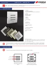
Page 19: ...EN 19 4 Package Contents Flush Shutter Device Installation Manual ...

Page 20: ... USA Qubino Other names Single pole single throw SPST One switch controlling one light circuit of lights One way switch Two way switch regular switch Toggle switch Switch Bi stable switch Single pole double throw SPDT Two switches controlling the same light circuit of lights Two way switch Three way switch Two way switch Used when you have three or more switches controlling the same light Intermed...

Page 21: ...EN 21 ...

Page 22: ... licensed and qualified electrician Please keep in mind that even when the device is turned off voltage may still be present in the device s terminals ⓘ Note Do not connect the device to loads exceeding the recommended values Connect the device exactly as shown in the provided diagrams Improper wiring may be dangerous and result in equipment damage Electrical installation must be protected by dire...

Page 23: ...ent electrical shock and or equipment damage disconnect electrical power at the main fuse or circuit breaker before installation and maintenance Be aware that even if the circuit breaker is off some voltage may remain in the wires before proceeding with the installation be sure no voltage is present in the wiring Take extra precautions to avoid accidentally turning the device on during installatio...

Page 24: ...EN 24 Step 2 Installing the device Connect the device exactly according to the diagrams shown below Before Qubino installation ...

Page 25: ...EN 25 After Qubino installation ...

Page 26: ...rom metal elements as they may cause signal interference Do not shorten the antenna The device s antenna should be as upright as possible This ensures the device s operational range is maximized up to 131 feet 40 m line of sight Step 3 Turn ON the fuse ...

Page 27: ...EN 27 Step 4 Add the device to your Z Wave network For more details on how to include the device please refer to the Z Wave Inclusion chapter ...

Page 28: ...EN 28 Step 5 The Installation is now complete It s time to make your life more comfortable with the help of the Qubino Flush Shutter ...

Page 29: ...it and forget it there is no need to worry about changing the batteries like with most other Z Wave temperature sensors which run on batteries The temperature sensor s range is between 25 80 C 13 176 F For more details about the temperature range see the manual for the temperature sensor The digital Temperature sensor comes with a 1 m 3 3 ft cord and a connector to attach it directly to a Qubino d...

Page 30: ...EN 30 Temperature sensor installation example Step 1 Exclude the device if it is already connected to your Z Wave system ...

Page 31: ...EN 31 Step 2 Switch of the power supply Step 3 Connect the temperature sensor as shown below ...

Page 32: ...EN 32 Step 4 Place the temperature sensor in the switch box Step 5 Turn the fuse on ...

Page 33: ...EN 33 Step 6 Re include the device to your network ...

Page 34: ...EN 34 Step 7 Start using the temperature sensor in connection with your device ...

Page 35: ...o the device page for more information If you still don t find what you re looking for click on the link to Qubino technical support team They will be able to automatically read the serial and part number from your device and quickly review the production log file containing the production date as well as any relevant device parameters and information This process allows our team to immediately id...

Page 36: ...40V mains power must be carried out only by authorized technicians with country specific knowledge of installation guidelines and norms and regulations The S Service button must NOT be used when the device is connected to a 110 240V power supply due to safety reason The module is connected to wires and other metallic parts connector screws where HIGH VOLTAGE is present Operating on module without ...

Page 37: ... the load connected Resistive loads light bulbs etc and loads that consume up to 4A the product s lifespan exceeds 70 000 toggles OVERLOAD PROTECTION Max Power Limit is automatically set by software When the current exceeds 4A for more than 5 seconds the load is automatically turned off An overload detected notification is sent to your gateway hub To reactivate the device power supply must be turn...

Page 38: ...ct the device to the power supply with the temperature sensor already connected 3 Toggle the switch connected to the I1 terminal 3 times within 3 seconds The device has to get On Off signal 3 times meaning 3 times push of the button or with the normal button 3 times On Off Perform this operation slowly waiting more than 0 5s between pushes OR If the device is powered by 24 VDC SELV supply press an...

Page 39: ...SELV supply press and hold the S Service button for max 2 seconds 5 Exclusion with the switch connected to I1 terminal is not limited by time 6 The device will be removed from your network but any custom configuration parameters will not be erased FACTORY RESET 1 Connect the device to the power supply 2 Within the first minute 60 seconds the device is connected to the power supply toggle the switc...

Page 40: ...en input I1 is pressed again Flush shutter sends Basic set OFF command to associated device and this device will turn OFF Group 3 Basic on off Triggered at change of input I2 up to 16 nodes In case parameter 1 is set to on off toggle when switch wired to input I2 is pressed Flush Shutter will send Basic set ON command to associated device and this device will turn ON when it is released Flush shut...

Page 41: ...ommand to associated device the command is actual position of blinds so the associated device will turn on same level as blinds are Example with association between Flush Shutter and dimmer when shutters blinds reach middle position 50 it will send switch multilevel set 50 command and dimmer will turn on 50 Group 8 Multilevel set Triggered at changes of value of slats tilting position up to 16 nod...

Page 42: ...asic set ON command to associated device and this device will turn On when input I2 is pressed again Flush shutter sends Basic set OFF command to associated device and this device will turn OFF Group 4 Basic on off Triggered at sensing moving direction of roller up FF down 00 up to 16 nodes When blinds are moving up Flush Shutter will send Basic set ON command to associated device and associated d...

Page 43: ...sition up to 16 nodes Flush Shutter device will send Switch multilevel set command to associated device the command is actual position of tilts Example with association between Flush shutter and dimmer When shutters tilts rotate to middle position 50 it will send switch multilevel set 50 command and dimmer will turn on 50 End point 3 External Temperature Sensor Group 1 Lifeline group 0 nodes allow...

Page 44: ...ull cycle up down and up again Slates tilting position calibration par 71 set to 1 When enabling venetian blinds mode position calibration for slats titling must be done After doing this the position and angle of the slates can be set By default full turn time for slates is set to 1 5s This value can be changed with parameter 72 1 Include and perform the device calibration process according to sec...

Page 45: ...ss of any push button will stop the movement Keeping the push button connected to I1 up pressed for more than 0 5 second long press initiates up movement until the push button is released Keeping the push button connected to I2 down pressed for more than 0 5 second long press initiates down movement until the push button is released Manual operation for Shutter with toggle switch par 71 set to 0 a...

Page 46: ...and par 1 set to 0 When toggle switch connected to I1 up is pressed initiates up movement until the toggle switch is released When toggle switch connected to I2 down is pressed initiates up movement until the toggle switch is released When the slats are on 100 and the quick press on UP is done the shutter move up When the slats are on 0 and and the quick press on DOWN is done the shutter move down...

Page 47: ...EN 47 When shutter is moving UP the slats are at 100 position When the shutter is stopped by push button or by Gateway the slats move to previous position before they start moving ...

Page 48: ...mands ALL ON ALL OFF that may be sent by the primary or secondary gateway hub within the Z Wave network Values size is 2 byte dec default value 255 255 ALL ON active ALL OFF active 0 ALL ON not active ALL OFF not active 1 ALL ON not active ALL OFF active 2 ALL ON active ALL OFF not active Parameter no 40 Watt Power Consumption Reporting Threshold for Q1 or Q2 Loads Choose by how much the power con...

Page 49: ... power consumption in Watts is reported 0 32767 seconds If 0 is entered by default energy consumption reports will not be sent to the gateway hub Values size is 2 byte dec default value 0 0 Power consumption reporting disabled 1 32767 1 32767 seconds Power consumption reporting enabled Report is sent according to time interval value set here Parameter no 71 Operating modes Choose between the two o...

Page 50: ...es Values size is 2 byte dec default value 150 1 5 seconds 0 tilting time disabled 1 32767 0 01seconds 327 67 seconds NOTE If the set time is too long and a full turn was already performed the device will start to move up or down for the remaining time Parameter no 73 Slats position This parameter is used to enable disable the slats to return to the previously set position after being activated vi...

Page 51: ...moving time is always when the Shutter is at its lowest position Set parameter 74 to 0 and move the Shutter using the up down push buttons or the main gateway hub UI to the lowest desired position When the Shutter reaches this position set the parameter 74 to the duration required by the Shutter to completely open or completely close the attached shutters At this point the Shutter can be moved up ...

Page 52: ...ition positioning the shutters with the slider through the UI will not display the correct position of the Shutter Parameter no 76 Motor operation detection Define the power consumption threshold at the end positions Based on this value the device will know that the shutters reached the limit switches Values size is 1 byte dec default value 30 30 W 0 The value 0 means that reaching a limit switch ...

Page 53: ... of the relays is switched ON is read from the device If there is no power consumption during the set time motor not connected damaged or requires longer time to start motor at the end position the relay will switch OFF This time is defined by entering it manually Values size is 1 byte dec default value 30 3s 0 time is set automatically 3 50 0 3seconds 5seconds 100ms resolution ...

Page 54: ...re Sensor Offset Settings Set value is added to or subtracted from the measured value to adjust the temperature report sent by an external sensor sold separately This parameter only applies to the Celsius temperature unit the Fahrenheit unit is currently not supported Values size is 2 byte dec default value 32536 32536 Offset is 0 C 1 100 Where 1 stands for 0 1 C and 100 stands for 10 0 C added to...

Page 55: ... not supported Values size is 1 byte dec Default value 5 0 5 C 0 Reporting disabled 1 127 Where 1 stands for 0 1 C and 127 stands for 12 7 C 15 Technical Specifications Power supply Alimentation électrique Netzspannung Strömförsörjning 110 240 Vac 10 50 60 Hz 24 30 VDC Rated load current resistive load Courant nominal charge résistive Nennstromstärke ohmsche Last Nominell lastström resistiv last 2...

Page 56: ...ereich des digitalen Temperatursensors Mätområde digital temperatursensor 25 80 C 13 176 F Operation temperature Température d utilisation Betriebstemperatur Drifttemperatur 10 40 C 14 104 F Intended transportation condition Conditions de transport prévues Beabsichtigte Transportbedingung Avsedd transportförhållande 40 70 C 40 158 F Distance Distance Reichweite Avstånd up to 40 m indoors 131 ft Ju...

Page 57: ... g 54g 0 99 oz 1 90 oz Electricity consumption Consommation électrique Leistung Elförbrukning 0 4 W For installation in boxes Pour installation dans des boîtes Zur Montage in Dosen För installation i box Ø 60 mm 2 36 in 2M Switching Commutation Schaltung Omkoppling Relay 2x Relais 2x Relais 2x Relä 2x Z Wave Repeater Répéteur Z Wave Z Wave Verstärker Repeater Z Wave repeater Yes Oui Ja Ja Degree o...

Page 58: ...ds Max current for cos φ 0 4 is 2 A at 250 Vac Supported loads Electric motor 400 W 240 Vac 200 W 110 Vac For power factor 0 4 In case of inductive loads it is reccomended to use RC snubber circuit Please contact Qubino support regarding marked load types Please check below for more information about RC snubber RC snubber RC Snubber function is to prevent arcing and welding of the relay contacts t...

Page 59: ... Capacitance Value 0 1 uF 0 22 uF Voltage 275 VAC Resistance Value Ohm 47 100 Power Rating W 1 2 Suggested RC snubber ISKRA KNR 1532 For more information please contact https support qubino com support home ...

Page 60: ...IFIC_V2 COMMAND_CLASS_SWITCH_ALL_V1 COMMAND_CLASS_SWITCH_BINARY_V1 COMMAND_CLASS_SWITCH_MULTILEVEL_V3 COMMAND_CLASS_METER_V4 COMMAND_CLASS_SENSOR_MULTILEVEl_V7 COMMAND_CLASS_NOTIFICATION_V5 COMMAND_CLASS_MULTI_CHANNEL_V4 COMMAND_CLASS_ASSOCIATION_2 COMMAND_CLASS_MULTI_CHANNEL_ASSOCIATION_V3 COMMAND_CLASS_ASSOCIATION_GRP_INFO_V2 COMMAND_CLASS_CONFIGURATION_V1 COMMAND_CLASS_MARK COMMAND_CLASS_SWITCH...

Page 61: ..._MULTILEVEL_V3 COMMAND_CLASS_METER_V4 COMMAND_CLASS_NOTIFICATION_V5 COMMAND_CLASS_ASSOCIATION_V2 COMMAND_CLASS_MULTI_CHANNEL_ASSOCIATION_V3 COMMAND_CLASS_ASSOCIATION_GRP_INFO_V2 COMMAND_CLASS_MARK COMMAND_CLASS_SWITCH_MULTILEVEL_V3 Endpoint 2 Device Class BASIC_TYPE_ROUTING_SLAVE GENERIC_TYPE_SWITCH_MULTILEVEL SPECIFIC_TYPE_CLASS_C_MOTOR_CONTROL Command Classes COMMAND_CLASS_ZWAVEPLUS_INFO_V2 COMM...

Page 62: ...NFO_V2 NOTE The Endpoint 3 command class list only applies if an external digital temperature sensor sold separately is connected to the TS terminal If the sensor is not connected the following command class is not supported by the device COMMAND_CLASS_SENSOR_MULTILEVEL_V7 Endpoint 2 is supported by the module only when the parameter no 71 is set to the value 1 and the module is excluded and re in...

Page 63: ...p BASIC REPORT AND MULTILEVEL SWITCH REPORT At 0 0x00 Unknown position 0xFE Known position 0x01 0x62 The position is approximated At 100 0x63 BINARY SWITCH SET Moving to 0 Binary Switch Set 0x00 Go to 0 Moving to 100 Binary Switch Set 0x00 STOP Moving to 0 Binary Switch Set 0x01 0X63 0xFF STOP Moving to 100 Binary Switch Set 0x01 0X63 0xFF Go to 100 COMMAND_CLASS_METER Default values o Rate Type 1...

Page 64: ...ules Operation is subject to the following two conditions 1 This device may not cause harmful interference and 2 this device must accept any interference received including interference that may cause undesired operation NOTE This equipment has been tested and found to comply with the limits for a Class B digital device pursuant to part 15 of the FCC Rules These limits are designed to provide reas...

Page 65: ...aste electrical and electronic equipment Directive do not dispose of this product as household waste or commercial waste Waste electrical and electronic equipment should be appropriately collected and recycled as required by practices established for your country For information on recycling of this product please contact your local authorities your household waste disposal service or the shop whe...

Reviews: