Quantum Composers 9730 Series, Operating Manual
The Quantum Composers 9730 Series is a cutting-edge device designed for precision timing and synchronization. To maximize its potential, it is crucial to have the comprehensive Operating Manual at your disposal. You can conveniently download the manual for free from our website, ensuring optimal usage of this remarkable product.
Share
Download


Reviews:
No comments
Related manuals for 9730 Series

SP2000
Brand: Saint Productions Pages: 16

165914
Brand: North Star Pages: 42

9510+ Series
Brand: Quantum Composers Pages: 3

RIO ZUNI
Brand: MIOX Pages: 9

PSS60/E
Brand: Winco Pages: 24

Aqua-6
Brand: A2Z Ozone Pages: 13

CHRONOGRAF
Brand: Frequency Central Pages: 5

XFG2000
Brand: Master Quality Power Pages: 15

Power WHISPERWATT DCA70USI2
Brand: MULTIQUIP Pages: 84

NM PLUS
Brand: VICI DBS Pages: 41
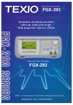
TEXIO FGX-293 Series
Brand: Kenwood Pages: 4

Magic Weld 200
Brand: Mosa Pages: 38

Porta Power
Brand: Edwards Pages: 33

ED1000
Brand: Honda Pages: 35

TGH 2300
Brand: Texas Pages: 23

030547-01
Brand: Briggs & Stratton Pages: 84

SMCVB-K163
Brand: R&S Pages: 92

HY30i
Brand: TOOLINE Pages: 36


