Pvelectronics Nixie QTC, User Manual
Introducing the Pvelectronics Nixie QTC, a cutting-edge electronic device that combines modern functionality with vintage charm. Enhance your space with this retro-inspired, eye-catching nixie clock. Want to fully unlock its potential? Look no further than the comprehensive User Manual, available for free download from manualshive.com. Master the art of timekeeping at your fingertips!
Share
Download


Reviews:
No comments
Related manuals for Nixie QTC
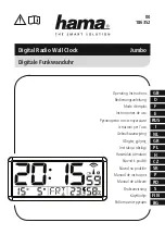
Jumbo
Brand: Hama Pages: 40

RM832A
Brand: Oregon Scientific Pages: 2

Echo DigiWake
Brand: Hearing Products Pages: 2

SONOCLOCK SC 910
Brand: Grundig Pages: 11

TCR4964
Brand: TruTech Pages: 13

00582W
Brand: Chaney Instrument Pages: 4

IR 380
Brand: iTronics Pages: 26

CR-A68
Brand: Coby Pages: 1

ME 3105
Brand: Trevi Pages: 8

AJ3019/04
Brand: Philips Pages: 2

AJ3017/05
Brand: Philips Pages: 2

AJ3005/00
Brand: Philips Pages: 2

IV-22
Brand: Nixie Clock Pages: 4

Dream Machine ICF-C743
Brand: Sony Pages: 2

DREAM MACHINE ICF-C390
Brand: Sony Pages: 9

DREAM MACHINE ICF-C295
Brand: Sony Pages: 9

Dream Machine ICF-C290
Brand: Sony Pages: 13

Dream Machine ICF-C490
Brand: Sony Pages: 16


