PureAire Universal Gas Detector, Instruction Manual
The PureAire Universal Gas Detector comes with an easy-to-understand Instruction Manual, allowing users to confidently set up and operate the product. For a hassle-free experience, the user manual is available for free download at manualshive.com, providing you with comprehensive guidelines to ensure optimal usage of this exceptional gas detection device.
Share
Download


Reviews:
No comments
Related manuals for Universal Gas Detector

CS100
Brand: Velleman Pages: 16

HGM300
Brand: Bacharach Pages: 8

Sierra Madre
Brand: White's Pages: 32

ACE 150
Brand: Garett Pages: 18

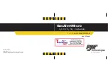
BW Clip Real Time
Brand: Honeywell Pages: 4
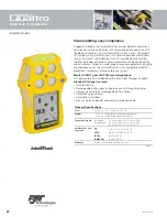
BW GasAlertQuattro
Brand: Honeywell Pages: 6
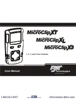
BW GasAlertMicroClip X3
Brand: Honeywell Pages: 68

BW Flex Series
Brand: Honeywell Pages: 61
BW GasAlertMicro
Brand: Honeywell Pages: 83

BW GasAlert MicroClip X3
Brand: Honeywell Pages: 68
BW GasAlertMicro 5
Brand: Honeywell Pages: 113

AreaRAE Plus
Brand: Honeywell Pages: 145

EW-401
Brand: ewoo Pages: 10

GDWBI20A00
Brand: Carel Pages: 52

SW-238
Brand: Conrad Pages: 14

Gamma Sports 6000
Brand: Teknetics Pages: 24

eurotek Pro
Brand: Teknetics Pages: 24

G2
Brand: Teknetics Pages: 36


