background image

Practice Section 1631

Issue 4, October 2009

1

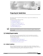
Figure 1. O3-4D1L3 U2 Unit

2

1

DS1-1

RS-232

4

3

C
R
A

F
T

DS1

EN

O3-4D1L3

R
X

OC3

UNIT

DS1-4

T
X

DS1-3

DS1-2

U2

UPDATE

1. INTRODUCTION

This practice describes the Pulsecom

®

O3-4D1L3 U2 OC3 to DS1 Multiplexer, shown in

Figure 1. Installation instructions and engineering references are included.

CONTENTS

PAGE

1.

INTRODUCTION . . . . . . . . . . . . . . . . . . . . . . . 1

A. Reason for Reissue . . . . . . . . . . . . . . . . . . 2

B. Description . . . . . . . . . . . . . . . . . . . . . . . . . 2

C. Features. . . . . . . . . . . . . . . . . . . . . . . . . . . 3

2.

APPLICATIONS . . . . . . . . . . . . . . . . . . . . . . . . 4

3.

FUNCTIONAL DESCRIPTION . . . . . . . . . . . . . 5

A. OC3 Circuitry . . . . . . . . . . . . . . . . . . . . . . . 5

B. DS1 Circuitry . . . . . . . . . . . . . . . . . . . . . . . 6

C. Local Alarms . . . . . . . . . . . . . . . . . . . . . . . 6

4.

INSTALLATION . . . . . . . . . . . . . . . . . . . . . . . . 9

A. Controls and Indicators . . . . . . . . . . . . . . 10

B. Select and Install Mounting . . . . . . . . . . . 13

C. Make Alarm Connections. . . . . . . . . . . . . 13

D. Install O3-4D1L3 Transceiver and Unit . . 13

E. Make OC3 Connections. . . . . . . . . . . . . . 14

F. Make DS1 Connections . . . . . . . . . . . . . . 15

5.

CRAFT PORT . . . . . . . . . . . . . . . . . . . . . . . . 16

A. Access . . . . . . . . . . . . . . . . . . . . . . . . . . . 16

B. Provisioning . . . . . . . . . . . . . . . . . . . . . . . 18

C. Manual Loopbacks. . . . . . . . . . . . . . . . . . 20

6.

SPECIFICATIONS . . . . . . . . . . . . . . . . . . . . . 20

7.

MAINTENANCE . . . . . . . . . . . . . . . . . . . . . . . 21

8.

CUSTOMER SERVICE . . . . . . . . . . . . . . . . . 22

OC3 TO DS1 MULTIPLEXER

O3-4D1L3 U2

Multiple Patents Pending

Trademarks used in this manual:

AMP and CHAMP are trademarks of AMP Inc.
CLEI is a trademark of Telcordia Technologies, Inc.
Microsoft and Windows are registered trademarks of Microsoft, Inc.
Pulsecom is a registered trademark of Hubbell Inc.

©2009 Pulse Communications Inc. All rights reserved.

Summary of Contents for O3-4D1L3

Page 1: ...6 C Local Alarms 6 4 INSTALLATION 9 A Controls and Indicators 10 B Select and Install Mounting 13 C Make Alarm Connections 13 D Install O3 4D1L3 Transceiver and Unit 13 E Make OC3 Connections 14 F Ma...

Page 2: ...D1L3 U2 will be referred to as the O3 4D1L3 Table 1 O3 4D1L3 U2 Board and OC3 Transceiver Ordering Codes Ordering Code CLEITM Code Wave length Link Loss Budget Maximum Output Level Maximum Input Level...

Page 3: ...B 7 5 dB and 15 dB Support for ESF data link and craft port loopback commands DS1 superframe SF ESF and unframed operation support Instant Default feature that permits restoring all settings to their...

Page 4: ...igh Bit Rate Digital Subscriber Line HDSL Facilities to Fiber With Type 3192 O3 4D1L3 and Type 400 O3 4D1 Units Figure 2 O3 4D1L3 Typical Applications SONET Mux D S X O3 4 D1 D S X O3 4 D1 D S X O3 4...

Page 5: ...oad is not modified Figure 3 shows a functional block diagram A OC3 Circuitry The optical interface for the 155 Mbps data stream conforms to the basic SONET structure defined in GR 253 CORE Figure 3 O...

Page 6: ...able a 24 minute loopback timeout for the four DS1 lines The craft port can be used to selectively inhibit loopback as well as loopback timeout on a per DS1 basis See Section 5 CRAFT PORT for addition...

Page 7: ...lay TX AIS upstream DS1 3 LOS alarm in craft port System B DS1 4 LOS DS1 4 LED yellow DS1 4 drop AIS DS1 4 AIS FE alarm in craft port DS1 LED red DS1 alarm relay TX AIS upstream DS1 4 LOS alarm in cra...

Page 8: ...tream System B DS1 2 LOS DS1 LED yellow DS1 2 drop AIS DS1 2 AIS FE alarm in craft port DS1 LED red TX DS1 2 AIS upstream System B DS1 3 LOS DS1 LED yellow DS1 3 drop AIS DS1 3 AIS FE alarm in craft p...

Page 9: ...nge transceiver is used in an application with short fibers a 15 dB attenuator should be installed on the transmit port to prevent bit errors and possible damage to the receiver 5 When connecting the...

Page 10: ...OC3 output transmit LC optical connector CRAFT RS 232 DB 9 female port for access to PC running HyperTerminal or other VT 100 emulation program Switch Function EN 1 2 3 4 Selects Enable or Disable op...

Page 11: ...s to their default values Note that the initial position of S1 1 is not important the O3 4D1L3 detects a change in the position of S1 1 during power up as an instruction to restore parameters to their...

Page 12: ...Dry Contact 9 Ring Dry Contact DS1 Alarm F Tip1 Dry Contact 6 Ring1 Dry Contact Power 8 48 VDC IN 5 48V Return IN Ground J Frame GND IN Figure 6 Switch Positions on the O3 4D1L3 RING1 DS1 ALM A 1 B 2...

Page 13: ...iver and module Procedure 1 Making Optional Alarm Connections STEP ACTION 1 Wire local OC3 alarms to backplane connector pins K and 9 Tip and Ring 2 Wire local DS1 alarms to backplane connector pins F...

Page 14: ...ective and should be replaced 2 Remove the protective dust cover from the front panel OC3 LC jack labeled RX TX 3 Plug in the OC3 fiber cable 4 If the far end OC3 connection has already been made the...

Page 15: ...it is defective and should be replaced 3 If the Pulsecom AMP MSL U24Sxxx assembly is used refer to Practice Section 1636 4 If the far end DS1 cable connection has already been made to an active DS1 de...

Page 16: ...s The following items are required for performance monitoring 486 PC or better computer with 24 Mbytes minimum of RAM Microsoft Windows 95 or higher HyperTerminal or compatible VT 100 terminal emulati...

Page 17: ...t program 5 At the Name prompt in the Connection Description dialog box type O3 4D1L3 Then select an icon that you wish to represent the O3 4D1L3 to simplify future access Next click the OK button to...

Page 18: ...ord prompt type root Then hit the ENTER key Table 8 O3 4D1L3 Provisioning Feature Option Default A DS1 Provisioning Name Permits assigning a 12 character name to each DS1 DS1 1 2 3 4 Framing Format Su...

Page 19: ...band loopback codes when provisioned for NT and SF operation the unit will only respond to in band loopback codes See Table 9 Figure 8 DS1 Loopbacks Table 9 Loopback Requests A SF Configuration In Ban...

Page 20: ...manual loopback are available for use via the craft port These loopbacks can be accessed via the Maintenance Manager sub menu Network toward optical interface Customer toward DS1 interface Bilateral t...

Page 21: ...Impedance 100 ohms 5 balanced Line Rate Tolerance 1 544 Mb s 130 ppm Frame Format SF ESF or unframed Pulse Amplitude 3V 10 Pulse Width 324 ns 30 ns Line Build Out 0 to 655 feet 0 7 5 or 15 dB Alarm In...

Page 22: ...concerning the operation of the unit to Pulsecom Technical Support If the unit is defective limit field repair to replacement of the plug in module or SFP transceiver Obtain repair services by returni...

Reviews: