Proslogan IU-4009, User Manual
The User Manual for Proslogan IU-4009 is available for free download on manualshive.com. This comprehensive manual provides step-by-step instructions and detailed information on operating and maintaining the product. Get your free manual now and unleash the full potential of Proslogan IU-4009!
Share
Download


Reviews:
No comments
Related manuals for IU-4009

SD-10
Brand: ZF Pages: 28
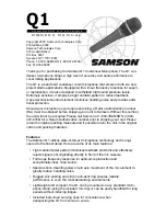
Q1
Brand: Samson Pages: 4

MR-400/M
Brand: Ude Pages: 3

WHAM
Brand: Uniden Pages: 20

COBY CX-CD375
Brand: Coby Pages: 1

Beta 53
Brand: Shure Pages: 34

HM-45
Brand: Nady Systems Pages: 2

Any Spot
Brand: CTS Pages: 20

APEX181
Brand: Apex Digital Pages: 1

31 24 89
Brand: MC Crypt Pages: 65

CX-500HQ
Brand: JTS Pages: 2

RV-DP200
Brand: JVC Pages: 62

PGX-D 14
Brand: Sound Projections Pages: 2

BTB8000
Brand: Philips Pages: 24

BTB2670
Brand: Philips Pages: 24

MwmU-5
Brand: MouKey Pages: 6

SKM 9000
Brand: Sennheiser Pages: 109

unipoint U891RC
Brand: Audio Technica Pages: 1


