


PRONAR Sp. z o.o.
17-210 NAREW, UL. MICKIEWICZA 101A, PODLASKIE PROVINCE
phone:
+48 085 681 63 29
+48 085 681 64 29
+48 085 681 63 81
+48 085 681 63 82
fax:
+48 085 681 63 83
+48 085 682 71 10
www.pronar.pl
OPERATOR'S MANUAL
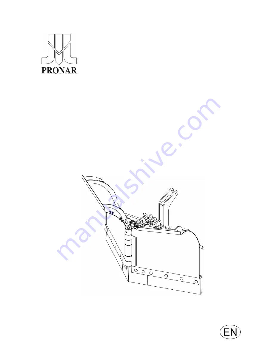
SNOW PLOUGH
PRONAR PUV-1400
TRANSLATION OF THE ORIGINAL COPY OF THE MANUAL
EDITION 1A-11-2011
PUBLICATION NO 305N-00000000-UM
Summary of Contents for PUV-1400
Page 2: ......
Page 3: ...SNOW PLOUGH PORNAR PUV 1400 MACHINE IDENTIFICATION TYPE SERIAL NUMBER ...
Page 6: ......
Page 9: ...SECTION 1 BASIC INFORMATION ...
Page 19: ...SECTION 2 SAFETY ADVICE ...
Page 28: ...PUV 1400 SECTION 2 2 10 ...
Page 29: ...SECTION 3 DESIGN AND OPERATION ...
Page 36: ...PUV 1400 SECTION 3 3 8 ...
Page 37: ...SECTION 4 CORRECT USE ...
Page 53: ...SECTION 5 MAINTENANCE ...
Page 65: ...NOTES ...
Page 66: ......


