


PRONAR Sp. z o.o.
17-210 NAREW, UL. MICKIEWICZA 101A, WOJ. PODLASKIE
tel.:
+48 085 681 63 29
+48 085 681 64 29
+48 085 681 63 81
+48 085 681 63 82
fax:
+48 085 681 63 83
+48 085 682 71 10
www.pronar.pl
OPERATOR’S MANUAL
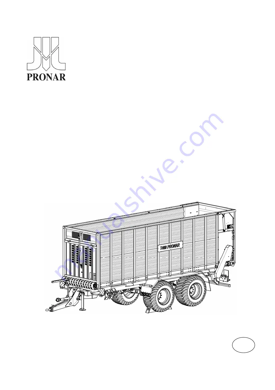
TRAILER
PRONAR T400
TRANSLATION OF THE ORIGINAL DOCUMENT
ISSUE 2A-11-2013
PUBLICATION NO. 252N-00000000-UM
EN
Summary of Contents for PRONAR T400
Page 2: ......
Page 6: ......
Page 11: ...CHAPTER 1 BASIC INFORMATION ...
Page 26: ...Pronar T400 CHAPTER 1 1 16 ...
Page 27: ...CHAPTER 2 USERS SAFETY ...
Page 45: ...CHAPTER 2 Pronar T400 2 19 Figure 2 3 Information and warning decals positioning ...
Page 46: ...Pronar T400 CHAPTER 2 2 20 ...
Page 47: ...CHAPTER 3 STRUCTURE AND PRINCIPLES OF OPERATION ...
Page 69: ...CHAPTER 4 PRINCIPLES OF USE ...
Page 86: ...Pronar T400 CHAPTER 4 4 18 ...
Page 87: ...CHAPTER 5 TECHNICAL SERVICE ...
Page 119: ...CHAPTER 5 Pronar T400 5 33 Figure 5 13 Greasing points ...
Page 120: ...Pronar T400 CHAPTER 5 5 34 Figure 5 14 Greasing points suspension ...
Page 135: ...NOTES ...
Page 136: ... ...
Page 138: ......


