Promise Technology VTrak J630s, Product Manual
The Promise Technology VTrak J630s user manual is available for free download on our website. This comprehensive product manual provides detailed instructions, troubleshooting tips, and essential information to maximize the functionality of your VTrak J630s storage system. Get the most out of your product by downloading the manual from manualshive.com.
Share
Download


Reviews:
No comments
Related manuals for VTrak J630s

100 Series
Brand: Cactus Pages: 27

X1
Brand: XenData Pages: 12
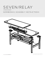
SEVEN
Brand: WATSON Pages: 12

WY51100
Brand: Wanroy Pages: 24

UltraHD 20296
Brand: Seville Classics Pages: 7

1921567
Brand: Keter Pages: 76

QUICKVIEW 300
Brand: Maxtor Pages: 73

UTASC1015
Brand: oldfields Treco Pages: 28

QuantaGrid D51PH-1ULH
Brand: QCT Pages: 167

ARCFlash
Brand: Archos Pages: 12

Storwize V5000E
Brand: IBM Pages: 120

Fireball LCT20
Brand: Quantum Pages: 2

SD-0512
Brand: Argus Pages: 1

Memorator Pro 5xHS
Brand: Kvaser Pages: 27

Pavilion 4500 - Desktop PC
Brand: Seagate Pages: 2

Momentus ST160LT003 - 9YG141
Brand: Seagate Pages: 40

ST3120026A-RK - Barracuda 120 GB Ultra ATA/100 Hard Drive
Brand: Seagate Pages: 2

Medalist 10231
Brand: Seagate Pages: 40


