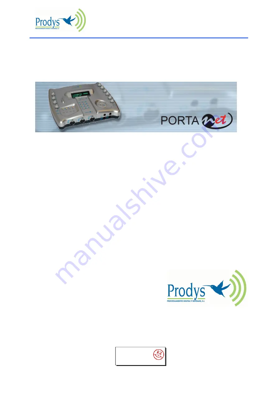
background image

    PortaNet


                                                                             User Manual


PortaNet


User Manual 

Ver. 5.4.1.2


interstage

Phistersvej 31, 2900 Hellerup, Danmark

Telefon 3946 0000, fax 3946 0040

www.interstage.dk

-

 pro audio with a smile

Summary of Contents for PortaNet

Page 1: ...PortaNet User Manual PortaNet User Manual Ver 5 4 1 2 interstage Phistersvej 31 2900 Hellerup Danmark Telefon 3946 0000 fax 3946 0040 www interstage dk pro audio with a smile ...

Page 2: ...pply 17 PortaNet audio inputs 19 IV 1 Location 19 IV 2 Technical specifications 19 IV 2 1 MIC LINE level inputs 19 IV 2 2 International Sound LINE level input 19 IV 3 Audio Level Controls 20 IV 4 Audio input configuration 20 IV 4 1 ON keys 20 IV 4 2 TB Keys 20 PortaNet audio Outputs 22 V 1 Location 22 V 2 Headphone outputs 22 V 2 1 Technical specifications 22 V 2 2 Operation mode Headphones Matrix...

Page 3: ...mmunication interfaces 35 VII 6 Connecting PortaNet to the line 35 VII 7 Audio checking 36 VII 8 Selecting the compression algorithm 37 VII 9 Decoder operation 37 VII 10 Calling from PortaNet 37 VII 10 1 CALL1 CALL2 and Phone Book keys 38 VII 10 1 1 Establishing a call when PortaNet is configured as an IP Unicast Multicast codec 39 VII 10 1 2 Establishing a call when PortaNet is configured as an I...

Page 4: ...ng 78 VIII 4 1 Locking the keypad from the Portanet keyboard 79 VIII 5 Audio control keypad 79 VIII 6 Scheduler 80 VIII 6 1 Configuration 80 VIII 6 2 How to enable disable the Scheduler 80 VIII 6 3 Automatic and manual call 81 VIII 6 4 Programming the scheduler 81 VIII 6 5 Name 82 VIII 6 6 Start 82 VIII 6 7 Priority 82 VIII 6 8 End 82 VIII 6 9 Scheduled call configuration 85 VIII 6 9 1 Manual conf...

Page 5: ...04 IX 6 1 UNICAST communications 104 IX 6 2 Using line 2 104 IX 6 3 Establishing a UNICAST connection from the PortaNet 105 IX 6 4 Establishing a MULTICAST communication from the PortaNet 105 IX 6 5 MULTI UNICAST 107 IX 6 6 Prodys Proprietary set of protocols 108 IX 6 7 Proprietary set of protocols v2 109 IX 6 8 PRODYS PORTS for Prodys Proprietary protocols v1 v2 111 IX 7 SIP 111 IX 8 SAP 113 IX 9...

Page 6: ... XII 1 4 Audio distortion 137 XII 2 ISDN communication problems 137 XII 2 1 Unit cannot make outgoing calls 137 XII 2 2 Unit cannot receive incoming calls 138 XII 3 IP communication problems 138 XII 3 1 Prodys Codec s Web Page cannot be accessed 138 XII 3 2 When connecting two audiocodecs in unicast there is no audio at one end 141 XII 3 3 No audio when connecting two audiocodecs using Multicast 1...

Page 7: ... XIV 2 Headphone outputs 151 XIV 3 Aux output 151 XIV 4 Rec output 151 XIV 5 LAN port 152 XIV 5 1 Connecting to a HUB or SWITCH 152 XIV 5 2 Connecting to a PC 152 XIV 6 RS 232 port 153 XIV 7 GPIO Port 153 Updating the firmware 154 ...

Page 8: ...same or equivalent type recommended by the manufacturer Dispose of used batteries according to the manufacturers instructions Your product is designed and manufactured with high quality materials and components which can be recycled and reused When this crossed out wheeled bin symbol with black bar underneath is attached to a product it means that product is covered by the European Directive 2002 ...

Page 9: ...mental understanding about the main features and operation modes This manual is arranged in the following manner 1 PortaNet general specifications 2 Installing the PortaNet 3 Operation guide 4 Remote control 5 PortaNet blocks 6 How it works 7 Examples of applications 8 Problem solving guide 9 Technical specifications 10 Connectors 11 Updating the firmware ...

Page 10: ...o adapt to the needs of different applications Compression algorithms PortaNet is equipped with the widest range of compression algorithms without any additional cost G711 G722 PCM MPEG1 2 Layer II Mpeg 1 2 Layer III MPEG 2 4 AAC LC MPEG4 AAC LD MPEG4 AAC HE Standard and Enhanced apt X Communications IP and ISDN connectivity With PortaNet it is possible to establish two independent connections one...

Page 11: ...ort any damage to the shipping company immediately Unpack the unit carefully if you find any damage or the unit does not work correctly you should contact Prodys or its distributor as soon as possible III 1 PortaNet overview PortaNet has all its connections in its front and rear panels The keypads and display are placed in the top surface III 1 1 Control Panel ...

Page 12: ...nu Keypad Navigation Keys The keys are used for moving around the menus and the OK is for selecting accepting the desired action or parameter Inf key This key allows the user a simple and quick way to display detailed information on the status and configuration of the PortaNet Call management keypad The numeric keypad is for entering information such as the IP address or ISDN number that you wish ...

Page 13: ...us of each input OFF Input disabled Green Input enabled and connected to the program line line 1 Red Input enabled and connected to the TalkBack line line 2 Power LED It shows the power supply status and also battery status GREEN The external power converter is powering the unit The battery is not connected BLINKING ORANGE The external power converter is powering the unit The battery is connected ...

Page 14: ... configured to work as a MIC level input ph swtich 48 volts Phantom powered When this switch is in the UP position OFF this option is disabled When this switch is in the down position ON this option is enabled Headphone outputs There are three headphone outputs each one related to its corresponding audio input Signals present on the headphone audio outputs will be dependent on the configuration of...

Page 15: ...or MIC level and it has the possibility to be phantom powered 48 volts However it doesn t have a headphone output related For this purpose the aux output might be used III 1 3 1 1 LINE level input International Sound Input Int in This is an additional line level input which can be mixed with the headphone outputs to provide the international sound to the commentators III 1 3 2 Second auxiliary lin...

Page 16: ...d compatible with ISDN Pronto2 3 Prodys devices select Pronto2 3 format When selecting IP as communication interface the auxiliary data can be sent via a different path different from the audio one This method has 3 big advantages less delay independent from the audio codification delay the possibility to send receive auxiliary data regardless of the compression mode used for the audio communicati...

Page 17: ...5 connector for connecting to an S T interface S T S0 There is available a special version with U ISDN interface III 1 3 6 Power supply PortaNet comes supplied with a desk top AC DC converter 16 volts output to be connected to the power connector located at the rear panel The power converter works with an AC input range of 100 to 240 VAC 50 to 60 Hz The power switch is located just below the power...

Page 18: ...and it is being charged on the system ORANGE The external power converter is not powering the unit The battery is connected and powering the unit BLINKING RED The external power converter is not powering the unit The battery is connected and powering the unit but it is about to run out about 20 minutes 10 of battery capacity Once the unit is switched on the boot sequence will start This sequence w...

Page 19: ...levels by means of a switch placed on the right side of the input connector It is possible to supply phantom power 48 volts to each input There is a switch on the left side of the input connector for this purpose When the audio inputs are configured as MIC level inputs sensibility range is 60 to 25 dBu When phantom power is enabled the whole gain is decreased by 15 dB to compensate for the the hig...

Page 20: ...he audio sent through the program line line 1 The corresponding LED will light on GREEN indicating that the input is enabled and going through the line 1 IV 4 2 TB Keys PortaNet supports two independent communications via IP or ISDN Thus we can establish one connection for the main program and another one for coordination or TalkBack program Each input can be configured to be added to the audio co...

Page 21: ...ut is disabled for security reasons This way this input cannot enter the program line unintentionally However it is possible to change this operation mode from the web page When the Recover Last Mode is selected the input will recover its previous status when it leaves the TalkBack line ...

Page 22: ... Maximum output level 6dBu 8 mW on 300 ohms THD N 0 01 1kHz SNR 95 dB Independent audio sources local o return for left and right Independent level adjustment for each output V 2 2 Operation mode Headphones Matrix The audio sources for the headphones can be selected from the PortaNet web browser At the same time it is possible to define if some of them will be attenuated depending on which line pr...

Page 23: ...x Tb Tx Following is showed the dialog to select the headphones configuration By right clicking on each cross point a new dialog appears that allows to define the behaviour of the selected output depending on where the corresponding input is connected that is depending on if the MIC LINE level input is connected ...

Page 24: ...era Program Cue or International Sound can be attenuated when the corresponding input is connected to the Talkback channel It is possible to define an independent attenuation level for either of them The same thing can be done regarding Talkback Tx and Talkback Rx that is either signal can be attenuated when the corresponding input goes to program V 2 2 2 Enable from TB Key Enable from Tb Key is a...

Page 25: ...from the PortaNet web browser V 3 1 Technical specifications Bandwidth 20Hz 20kHz 0 3dB Maximum audio level 20dBu THD N 0 005 1kHz SNR 100 dB XLR male connector fitted to the rear panel In normal operation this output carries the audio coming from the program line line 1 This audio signal is called CUE Output impedance 50 ohms V 3 2 Operation Modes The REC output supports two different configurati...

Page 26: ...channel audio of the received stereo signal This operation mode requires to be enabled from the web browser in order to disable the compressor limiter For more information please read the chapter XI Operation examples V 3 3 RECORDING operation mode In this mode it is possible to add the audio contribution signals on the program line to the return signal from the same line CUE signal One applicatio...

Page 27: ...iguration matrix of the web browser V 4 1 Technical specifications 6mm 1 4 jack connector at the front panel Bandwidth 20Hz 20kHz 0 3dB Maximum output level 20dBu THD N 0 005 1kHz SNR 100 dB Output impedance 50 ohms V 4 2 Operation modes Depending on which signals are selected from the auxiliary output configuration the AUX output supports different configurations ...

Page 28: ...ains the signal coming from the second line Talkback Rx V 4 2 2 INTERCOM mode In this mode the audio signal going through line 2 Talkback Tx is added to the AUX output V 4 2 3 Other configurations for the Intercom mode This diagram shows all the signals which can be routed to the aux output ...

Page 29: ...VI 1 What is an audio preset An audio preset contains all the configuration of the following items Audio inputs It includes whether the audio input levels are remotely controlled or not and if so the audio input level configuration Audio Auxiliary output the configuration for each audio Auxiliary output REC and AUX outputs Headphone outputs the configuration of the headphone outputs according to t...

Page 30: ...e Configuration menu and the click on the New button A new pop up window makes possible to save the current settings and any further modification and to store with the Preset label of your choice by default Preset Once the name of the new preset has been added to the list it is necessary to press Ok or Apply in order for the audio preset to be stored The new audio preset will be created with the c...

Page 31: ... will not disturb the current audio settings in operation Note While the current audio configuration matches one of the stored Presets this will be indicated on the second line of the Preset Configuration panel as Current Preset Any mismatch between the Preset Configurations and the actual audio configuration forces the indication Current Preset none VI 3 Loading a preset Once a preset has been se...

Page 32: ...nection DOWN There is no link line plugged into the unit The cable is not plugged in correctly or there is an fault on the line VII 2 Checking the configuration the inf key This key provides the user with a simple and quick way to display detailed information about the status and configuration of the PortaNet As the screen is not able to display all the information at once you can cycle through th...

Page 33: ...ithin the menu IP can be used for remote control monitoring of the unit even when NET ISDN When IP network is selected make sure that the unit has been configured to support two independent communications that is IPCODEC as Codec Double Simple should be used only for stereo communications M A I N M E N U N E T E N C C O N F I N F M A I N M E N U A U D P O R T S Y S B O O K S Y S C O N F D A T A K ...

Page 34: ...a Communication protocol Check that the selected protocol is compatible with the line provided by your Telco Most countries except the USA now use EISDN b Local number or LNUM An abbreviation for Local Number With this option it is possible to assign a different number to each of the lines available on the basic rate ISDN In this way we can automatically map incoming calls to each line as each lin...

Page 35: ...onfiguring the LAN port Before making a connection over any IP network it is necessary to configure the IP addressing parameters IP address netmask and gateway PortaNet allows the assignment of the IP parameters either manually or by DHCP Manually User must enter the following IP parameters manually 1 IP address 2 Mask 3 Gateway IP address Automatically The unit gets the configuration automaticall...

Page 36: ...the top panel measures the audio level just before the compressor limiter This level corresponds to the sum of all the inputs which contribute to the program line line 1 that means all those inputs whose led is on GREEN This Vu meter comprises several green leds and a red overload led The audio levels obtained from the display with the INF key are digital domain measurements The input levels are m...

Page 37: ...ifferences such as the line bandwidth When selecting the ENC option on the main menu the following screen appears The different options for the Encoder 1 are as follows AUT Automatic mode PCM Linear audio G711 G722 MPL2 MPEG 1 2 Layer II MPL3 MPEG 1 2 Layer III AAC2LC AAC MPEG 2 Low Complexity AAC4LC AAC MPEG 4 Low Complexity AAC4LD AAC MPEG 4 Low Delay AAC4HE AAC MPEG 4 High Efficiency Apt XTM St...

Page 38: ...will also show different information depending on the type of NET selected IP or ISDN Depending on the line s status CALL 1 and CALL 2 will function in the following way With the line disconnected a Initiation of a communication Pressing CALL 1 or CALL 2 will access the call initiation menu Depending on the type of NET selected IP or ISDN the dialog that you will see will vary Note that CALL 2 onl...

Page 39: ...nidirectional point to point communication where only the end which makes the call will send audio Unicast Unidirectional Rx This is a unidirectional point to point communication where the calling end will be the receiver Multicast Tx This is point to multipoint communication in which the calling end will join a multicast group as a transmitter Multicast Rx This is point to multipoint communicatio...

Page 40: ...ll display the following Group Redial is the only option available when calling from the front panel This option will try to re establish all previous connections both Tx and Rx CALL 2 key is not available under Multi Unicast mode 4 This option is available from version 5 2 1 onwards L A N L 1 M O D E M U L T I C A S T U N I C A S T L A N L 1 M O D E U N I D I R B I D I R L A N L 1 M O D E T x R x...

Page 41: ...main menu For making connections however the BOOK key works like this Pressing BOOK you enter the Address Book index Use the left and right navigation keys to go through the different entries in the Address Book index By pressing OK we select the item that is on screen Now the screen shows the number numbers to call or the IP addresses depending on which ones have been saved Pressing OK again will...

Page 42: ...e same compression modes Compression algorithms There are no restrictions regarding the available compression modes in any line Encoder and decoder can work in different modes independently Automatic and manual answer Incoming calls can be answered automatically or manually depending on the menu option ANS If the ANS mode is set to manual the corresponding CALL key must be pressed to accept the ca...

Page 43: ...with Prodys IP audio codecs In addition support for industry standard algorithms is provided under the Streaming Protocol tab in the Configuration window of PortaNet web page A preliminary version of all protocols defined as mandatory by the EBU group in their N ACIP Audio Contribution Over IP project is supported This project defines the standard to achieve interoperability between audio codecs o...

Page 44: ... User Manual 44 of 156 All the calls made from line 1 in ProntoNet or PortaNet will be received through line 1 All the calls made from line 2 in ProntoNet or PortaNet will be received through line 2 Capít ulo I ...

Page 45: ...ld be necessary to modify the network configuration of the computer on which the web browser is running Installation Requirements 1 Pentium 166 or higher 2 64MB RAM minimum 3 Operating Systems Microsoft Windows XP Microsoft Windows 2000 Microsoft Windows NT 4 0 Service Pack 6 or higher Microsoft Windows Millennium Edition ME Microsoft Windows 98 Microsoft Windows Vista 4 Microsoft Internet Explore...

Page 46: ...Explorer can be configured to block OCX objects installation and or execution So depending on the configuration of the web browser a message like the following might appear when first accessing the PortaNet web page Go to Internet Options in IExplorer click on Security tab and set prompt when downloading ActiveX signed and unsigned controls at Local and Internet zones ...

Page 47: ...s case a message indicating Incorrect Versions will appear as soon as the user click on Control or Monitor on the login page Click on F5 to skip the cache entries and access to the real web page Even after pressing F5 and depending on the IExplrorer configuration and or version this situation might continue In that case go to Internet Options in IExplorer click on General tab and delete temporary ...

Page 48: ...ortaNet from the Web Page Bear in mind that only one page at the same time can control the unit However it is possible to monitor the unit from several web browsers simultaneously If a unit is already being controlled by a web page and we try to get the control from another website a message will appear This message will indicate that the unit is already being controlled from another PC and the IP...

Page 49: ...unit will be available for the new controller Once the password is entered correctly the web browser will display the Home Page The Web page is arranged in the following main areas A General Configuration area B Keypad locking control C Audio keypad remote control D Audio encoding configuration and communication control E Alarms area F Monitor area ...

Page 50: ... time out in order to get the PortaNet control Base Port When PortaNet ports have been modified it will be necessary to change this parameter according to the new port configuration in order to get to access to the PortaNet web browser MORE ABOUT THE PORTANET PORTS Changing Portanet Ports The PortaNet configuration menu allows the user to configure which ports the unit will use for its TCP UDP IP ...

Page 51: ...n window The different options are arranged in the following way Interfaces To configure the PortaNet Ports Audio Different options regarding audio configuration can be set from this menu remote audio input level control headphone output configuration or audio presets for example Sys System configuration clock keypad locking Book To edit the phone book Scheduller To schedule calls Advanced Special...

Page 52: ...PortaNet supports RIP2 protocol This protocol allows the user to set an internal IP address in order that the unit can be identified regardless of the IP settings provided by the DHCP server DNS support By specifying the IP address of a DNS Server the user can make calls to names instead of IP addresses This new feature is available in any place where an IP address has to be entered For example th...

Page 53: ...S information can be obtained from a DHCP Server VIII 2 1 1 1 Ports It is possible to configure which ports the unit will use when selecting Prodys proprietary protocols for IP communications5 5 For more information please read chapter IX 6 6 Prodys Proprietary Protocols ...

Page 54: ...when changing the base port 1 To access the web page of the unit the new port has to be indicated in the http address bar of the web browser after the IP address separated by a colon http IP Web Port Example 192 168 0 10 8080 2 To log into the unit click on the advance features button of the login window and specify the base port which we want to connect to 3 When establishing a call the new base ...

Page 55: ...n its phone book with the IP address of the caller and the base port of the caller Example if the caller has the IP address 10 1 5 0 and its base port is 40011 in the receiver the following entry should be configured in its phone book VIII 2 1 1 2 SNMP configuration6 It is possible to set the SNMP community 6 This option is available from version 5 2 1 onwards ...

Page 56: ...ort Configuration It is possible to set speed and duplex configuration to the following values VIII 2 1 2 ISDN Terminal adaptor Configuration The first dialog allows the selection of the ISDN protocol There are four options Euro ISDN 5ESS DMS 100 and NAT1 ...

Page 57: ...o three numbers for each line that work as call filters meaning that the line will only connect to calls that come from these pre programmed numbers This option is found in the ISDN set up menus under CNUM Calling Number Local number It is also possible to assign a single number to each line in a way that the line will only respond to calls to this local number This can be used if you need to map ...

Page 58: ...omatically to connect the line 1 or line 2 as configured The user can select which entry of the book will be used for this purpose8 Disconnect Line 1 When this input is activated the PortaNet will proceed automatically to disconnect the line 1 Disconnect Line 2 When this input is activated the PortaNet will proceed automatically to disconnect the line 2 It is only useful when the PortaNet is worki...

Page 59: ... the Decoder 1 is Framed Decoder 1 NOT framed The output will be activated when the Decoder 1 is NOT Framed Decoder 2 Framed The output will be activated when the Decoder 2 is Framed It is only useful when the PortaNet is working in ISDN mode as a DUAL CODEC Decoder 2 NOT framed The output will be activated when the Decoder 2 is NOT Framed It is only useful when the PortaNet is working in ISDN mod...

Page 60: ...nsparent configuration only works with audio algorithms that support ancillary data and have been previously activated When a GPO is configured to monitor alarms Alarm active it is possible to select which alarm will enable this output ...

Page 61: ...accordance with the configuration available at that moment PLL This is a special option that allows you to select the PLL reference clock when NET IP Redial It is possible to configure a number of redials The PortaNet will try the connection in the following cases 1 The unit is trying the connection for the first time 2 The unit was connected and lost the connection because the line dropped or the...

Page 62: ...mpted to enter the password and the following message appears If the password is entered successfully the following message appears Monitor This option allows the user to hide or display additional information on the main window VU meters Indicates audio levels System Monitor voltages temperatures and fan operation Streaming Shows clock sync algorithm operation and Buffer Occupation Graph Real Tim...

Page 63: ...it is possible to customize the control of the units and to integrate them in a global management system The protocol is based on which can be managed through two different communication ports the LAN port and the RS232 B port For more information please read ProntoNet SDK User s Manual IP Codec Mode There are two different operation modes SIMPLE and DOUBLE mode In SIMPLE mode the unit will cannot...

Page 64: ... the unit is configured as an ISDN codec and the answer mode is set to manual VIII 2 2 1 TimeDate This option allows the user to synchronize time and date by using SNTP protocol Simple Network Time Protocol SNTP operates always in the client server model and for this reason PortaNet can work as SNTP server or SNTP client VIII 2 2 2 Password Whenever the web browser is started it is necessary to en...

Page 65: ...e the auxiliary data can be sent via a different path different from the audio one the auxiliary data are embedded in the audio frames This method has 3 big advantages less delay independent from the audio codification delay the possibility to send receive auxiliary data regardless of the compression mode used for the audio communication and the possibility to send receive the User bit of the AES ...

Page 66: ...ation according to the SNMP protocol These SNMP traps will notify alarm information that is an SNMP trap will be sent when an alarm is activated or deactivated with the time and type of alarm For this to happen alarms have to be enabled see chapter VIII 8 Alarms PortaNet can be fully monitored though SNMP protocol It is also possible to notify alarm events via email The user can send alarm informa...

Page 67: ...records the user name a telephone number optionally two an IP address There are up to 32 indexes It is not possible to store ISDN numbers and IP address in the same index The proceeding to edit a phone book index is as follows 1 To select one index by clicking on its area 2 To select ISDN numbers or IP Address depending on which network will be used Only it is possible to select one of them 3 To e...

Page 68: ...r one VIII 2 2 8 Scheduler The Scheduler allows the user to program calls to be made automatically For more information read chapter VIII 6 Scheduler VIII 2 2 9 Advanced Streaming Multicast Rejoin On Timeout IGMP protocol functionality Enable Hangup Confirmation If the value is 1 the application will ask confirmation before disconeccting the line Streaming Control Protocol Timeout When the link is...

Page 69: ... test tool to check in real time the bandwidth delay and jitter of the IP connection between two PortaNets To allow adjustment of the various transmission and reception parameters to optimize the unit to provide the best quality real time audio streaming for a particular network connection These tools are grouped in the following manner 1 Protocol 2 Transmission parameters 3 Reception parameters 4...

Page 70: ...ing protocol for creating modifying and terminating sessions with one or more participants For more information please check the proper section of this document SAP SAP is a protocol for broadcasting multicast session information CCS NetStart AudioStar VIII 2 3 2 Tx Audio This option allows the user to configure the audio transmission parameter TBP Time between packets and to know in advance the r...

Page 71: ...mission time between packets is minimum as well However the greater the TBP the less bandwidth is required less overhead but the more delay there will be in the connection Otherwise the smaller the TBP the smaller the packet size and the greater the overhead due to the IP headers in the packets With this tool the user can know beforehand the required bandwidth overhead packet size and delay for th...

Page 72: ...re some IP header fields to carry out QoS Streaming Packets Quality of Service This option allows the user to configure the value in the ToS field in the IP header This field can be used to carry out QoS in the network Streaming packets Time To Live Configure the Time To Live parameter ...

Page 73: ... reception buffer and so to compensate the jitter The maximum value for this buffer is 10 sc This value can be changed during the audio connection VIII 2 3 4 Test This tool allows the user to check in real time the upload download bandwidth delay jitter and packet loss in an IP link between two PortaNets This information will be used to adjust the streaming parameters in order to achieve the best ...

Page 74: ...s of the remote PortaNet This dialog stores the last used IP addresses 2 Select the test you wish to perform 3 To run the test just press the test button 4 The values will be shown in a graph as well as the max min last and mean avg values 4 Press STOP to stop the test or CLEAR to reset the readings 5 The user can limit the bandwidth used by the test tool ...

Page 75: ...sible to simulate the same packet rate and bandwidth as that configured for the audio connection12 An accurate figure of total bandwidth used audio data overhead can be obtained from the Audio Configuaration screen Once the test is finished it is possible to export the results to an XML file VIII 2 3 5 Real Time Monitoring It is possible to monitor the streaming operation in real time by ticking a...

Page 76: ... because the clock of the AD converter at the transmitter side which runs slower than the DA converter at the receiver side Buffer overflow might be caused by the opposite scheme The clock at the transmitter side is running quicker than the clock at the receiver side Prodys PPL adjustment mechanism is aimed at dealing with this clock jitter and thus to compensate for this variation and guarantee p...

Page 77: ...PortaNet User Manual 77 of 156 ...

Page 78: ...ut not the audio control keypad c Menu To Lock only menu keypad but not the dial and audio control keypad Moreover there are two more options related with the keypad locking in the Sys configuration menu Password protected This option allows to set up a password that will be necessary to unlock the keypad from the PortaNet keyboard AutoLock after 60 sec Once this option is enabled the complete key...

Page 79: ...ed remotely from the web page ON control Each MIC LINE audio input has a key to enable disable it When an input is enabled it will contribute to the audio being sent through the program line line 1 The corresponding LED will light on Green indicating that the input is enabled and going through the line 1 TB control PortaNet supports two independent communications via IP or ISDN Thus we can establi...

Page 80: ...e Scheduler configuration window the user has to click on Config on the web page and then select Scheduler in the general configuration window VIII 6 2 How to enable disable the Scheduler The Scheduler dialog has a checkbox which allows the activation deactivation of the Scheduler When the Scheduler system is disabled none of the scheduled calls will be made In addition each scheduled call can be ...

Page 81: ...lish a programmed call when this call has the same or higher priority than the current one The default priority for automatic calls is 1 and the default one for manual calls is 10 Manuals calls are those made by the user It is possible to modify the default priority for the manual calls from the Scheduler dialog by changing the value of the field Manual call priority VIII 6 4 Programming the sched...

Page 82: ...duled call or pattern will be enabled VIII 6 7 Priority By clicking on Priority the user can change the priority value assigned to the current entry More information about priorities can be obtained in chapter 2 2 VIII 6 8 End There are two methods to define how long the call will last Recurrence and duration and End date and Time o Recurrence and duration This option allows the programming of cal...

Page 83: ...ecurrence This section is divided in two different parts o Starts on This option establish the start date and time for the configured pattern o Ends on It is possible to establish the end of the configured pattern in three different ways Without end date after a certain number of repetitions or in an specific date By clicking on Preview and edit tab the user will obtain a calendar wherein those da...

Page 84: ...lick on Recurrence The following window will be displayed This window is arranged in two different sections Recurrence pattern This section permits the user to configure the period of time for this call to be repeated Ends on From here it is possible to establish the end of this recurrence It can be never or after an specific number of occurrences ...

Page 85: ...onfiguration It is necessary to configure the type of network the numbers and the compression mode that will be used for call establishment To do that the user can configure these parameters manually or automatically by getting them from one of the entries of the phone book VIII 6 9 1 Manual configuration To configure these parameters manually clic on Edit The following dialog will be displayed Fr...

Page 86: ...led calls To modify a pattern or scheduled call the user has to select one scheduled call from the Scheduler list on the Scheduler Configuration Window Then by clicking on Modify the user will be able to edit all the parameters related to the select pattern VIII 6 11 Deleting existing scheduled calls To delete a pattern or scheduled call the user has to select one scheduled call from the Scheduler...

Page 87: ... paste a pattern select one from the list and right click on it and select the option Paste Call s VIII 6 13 Monitoring scheduled calls When one call related to one of the patterns defined in the scheduler of the unit is established the message SCHEDULED CALL IN PROGRESS will be displayed on the web page for the duration of the call ...

Page 88: ...e the encoders and control the communications VIII 7 1 Selecting the NET interface By clicking on the Net area This option is only available when the lines are disconnected VIII 7 2 Configuring the Encoder The Audio Mode area shows the current encoder and decoder configuration By double clicking on the Encoder area the user can change the encoder configuration ...

Page 89: ...o change the compression mode during the connection or to make calls through the book entries with compression modes different from the former one VIII 7 3 Making calls By double clicking on the Tx or Rx connection area the user can access the call menu window Depending on the selected communication interface IP or ISDN different options appear When NET ISDN the following window is displayed ...

Page 90: ...l 90 of 156 The user can enter the ISDN number or can select an index from the Phone Book The encoder can be configured from this dialog as well To make the call click on Dial When NET IP the following window is displayed ...

Page 91: ...s a receiver The user can enter the IP address or can select an index from the Phone Book The encoder can be configured from this dialog as well It is also possible to discover automatically all Prodys IP codecs connected to the IP network In order to make easy the dialling operation over IP networks a new facility was included in the Dial window This new tool allows the discovering of the Prodys ...

Page 92: ...l Line The communication line is not physically detected Most likely the interface is not plugged in The Display shows DOWN Connected The line is connected An arrow will indicate if it is an incoming or outgoing call The duration of the call also is indicated Disconnected The line is detected physically but no connection is being made Beside the text appear the disconnection codes Calling In the p...

Page 93: ...coder Status The Decoder status is shown on the right side of the Audio Mode area The Decoder status Searching The decoder is not synchronized Framed The decoder is synchronized Idle The line is disconnected Not available Decoder not available ...

Page 94: ...he unit will check The unit will notify the occurrence of each of the selected alarms It is possible to configure the unit to send SNMP traps or emails to notify alarms information VIII 8 1 Selecting Alarms The unit supports many different alarms The selection menu is opened by clicking over the Alarm area ...

Page 95: ...coder is not framed but it was framed before The alarm will be activated also if the unit is turned off In this case the alarm will indicate the date and time when the decoder lost the synchronization that is when the unit was turned off The alarm will be activated until the unit is framed once the line is connected again If the connection is not possible the alarm will be marked as finished Decod...

Page 96: ...rms window is highlighted VIII 8 3 Alarms History The alarms are saved on the non volatile memory of the PortaNet It means that it is possible to know what happened on the past even if the unit was disconnected of the network The alarms history can be showed by clicking over the lamp or over History option in the alarm selection dialogue An historical report of alarms in html allows the user to pr...

Page 97: ...raps will be sent An SNMP manager located at this IP address will receive and process the information according to the SNMP protocol These SNMP traps will notify alarm information that is an SNMP trap will be sent when an alarm is activated or deactivated with the time and type of alarm For this to happen alarms have to be enabled see chapter VIII 2 2 5 Alarms PortaNet can be fully monitored thoug...

Page 98: ...III 8 4 2 Email From the alarm dialog the user can enter several e mail addresses where this information will be sent to inform about the changes in the status of any alarm It is also possible to define the sender address of the email ...

Page 99: ...tings available with the PortaNet a PortaNet operating as IP CODEC The PortaNet will be configured to establish communications via the Ethernet port using the IP protocol b PortaNet operating as ISDN CODEC The PortaNet will be configured to establish communications via a basic access ISDN connection The PortaNet has a multi protocol ISDN terminal socket ready for connection to a basic rate 2B D in...

Page 100: ...92 256 MPEG AAC LC LD 64 128 192 256 384 MPEG 4 AAC HE 24 32 48 56 64 128 IP aptXTM 64 128 192 256 384 2 Mono13 or 1 Stereo G711 64 G722 64 MPEG1 2 LII 64 128 MPEG1 2 LIII 64 128 MPEG 2 4 AAC LC 64 128 MPEG 4 AAC LD HE 64 128 ISDN aptXTM 64 2 Mono or 1 Stereo IX 3 PortaNet working as a DUAL CODEC over ISDN When we select ISDN as the communications interface it is possible to establish two totally ...

Page 101: ...will work as usual that means it can establish two independent MONO communications via IP In SIMPLE mode the unit can establish only one MONO or STEREO communications via IP In DOUBLE mode over IP the following restrictions will be applied 1 Encoder 1 and Encoder 2 can only be set in MONO 2 Encoder 2 assigned to line 2 can only be set in G722 This configuration can be set both from the menu and fr...

Page 102: ...G722 Needs G722 encoded audio since it is synchronised by means of statistical framework It does not work if encoder is configured to aptX AAC HE or J52 YES YES MPEG1 2 LII MPEG1 2 LIII MPEG2 4 AAC LC MPEG 4 AAC LD It does not work if encoder is configured to aptX AAC HE or J52 YES NO Mpeg AAC HE aptXTM aptX not with SIP SAP as IP protocols It is necessary that the Encoder is also configured to AA...

Page 103: ...because it is not possible to use it in any other combination 2 If we want to receive an algorithm that does not support automatic synchronisation it is necessary to configure the Encoder to the same algorithm 3 If we want the Encoder to switch to the algorithm detected by the Decoder the Encoder should simply be set to AUTO mode ...

Page 104: ... between two units bi directionally IX 6 2 Using line 2 There are two different operation modes SIMPLE and DOUBLE mode In DOUBLE mode the unit will work as usual that means it can establish two independent MONO communications via IP In SIMPLE mode the unit can establish only one MONO or STEREO communications via IP In DOUBLE mode over IP the following restrictions will be applied 1 Encoder 1 and E...

Page 105: ...protocols Prodys IP units use please read chapter IX 6 6 IX 6 4 Establishing a MULTICAST communication from the PortaNet With MULTICAST the calls must be made from both ends Both the sender of the data and all the receivers of the data must call to establish a connection to the multicast group The multicast operation can be shown in the following diagram To initiate audio distribution the role of ...

Page 106: ...in receiving data flowing to a particular group must join the group using IGMP All this is done automatically by PortaNet when establishing a connection Multicast traffic is rejected when going through the Internet since most IP servers on the Internet do not currently support the multicasting part of the protocol except when using VPNs because VPNs encapsulates IP packets as unicast frames so rou...

Page 107: ...t locations concurrently This functionality overcomes the lack of Multicast support on some networks To select this new feature open the new NET menu by clicking on the NET button at the top on the left in the web page The main window will show all the available connections Depending on the compression mode up to 10 Tx connections will be available MPEG L2 L3 y AAC Up to 10 Tx 1 Rx PCM G711 G722 A...

Page 108: ...as well as for the negotiation of the codec mode automatic audio synchronisation in all modes Prodys Real Time Protocol P RTP This is a protocol based on UDP used for the transmission of audio Prodys eXtended Real Time Protocol PX RTP This is a protocol based on UDP used for the transmission of multicast audio Prodys Upgrading Identifying Protocol This protocol is based on UDP and used to identify...

Page 109: ...on 1 Proprietary protocol version 1 will allow the user to get information about jitter and buffer usage but will not allow the user to obtain information about lost and disordered packets This information will be saved separately for each connection in RAM memory Up to 24 hours of data from different calls can be stored Once the connection is established the user can access the real time network ...

Page 110: ...onized to each other so that the user can move through all the data very easily Data from each connection is stored independently so that it is possible to access data from connections other than the current one In addition it is possible to delete export or import data from any previous call ...

Page 111: ...ming Tool TCP 50033 UDP 50033 External Protocol P XP TCP 50031 Control Port TCP 50035 Status Port It is possible to change these ports from the web configuration window Please for more information about port changing read chapter VIII 2 1 1 1 Ports IX 7 SIP The European Broadcast Union EBU is promoting the interoperability of audio codecs for any manufacturer For this purpose the use and the appli...

Page 112: ...on at this document SIP Port TCP IP port dedicated to SIP signalling for establishing updating or finishing a call Port 5060 is mandatory by the standard if direct calls without gateways are expected Audio Port TCP IP port dedicated to the RTP communication this is the actual port for the audio streaming payload By default the number 5004 is reserved If SIP server support is granted by your networ...

Page 113: ...IX 8 SAP When selecting SAP as communication protocol only multicast calls will be available point to multipoint In addition the user will have to indicate the announcement IP address and port on which the audio streaming is announced ...

Page 114: ...e case that these parameters are modified by the user they should be configured to the same values at both ends the sender and the receiver When making a call with SAP as communication protocol only Multicast Tx and Multicast Rx call types will be available To launch an audio streaming over IP with SAP the user shall select Multicast Tx as call type from the dialing window and type in the multicas...

Page 115: ...PortaNet User Manual 115 of 156 To receive this audio streaming the user shall select the Multicast Rx call type and will introduce the same Multicast IP address as the transmitter ...

Page 116: ...sented as 2B D The PortaNet identifies each B channel as Line 1 and Line 2 respectively The PortaNet can operate as DUAL CODEC which means it can establish two totally independent MONO communications via each B channel at 64 Kbps In this situation the PortaNet will be able to use two Encoders and two Decoders independently PortaNet is aimed to work as a MONO codec To configure the unit to work as ...

Page 117: ...s at 128 Kbps Each line needs to be connected independently using the CALL 1 and CALL 2 keys To disconnect a call press and hold the appropriate CALL key for more than one second IX 9 2 Receiving calls via ISDN In general you must bear in mind the following when dealing with incoming ISDN calls Automatic or manual response Incoming calls can be answered automatically or manually depending how the ...

Page 118: ...s 1 DUAL JOINT STEREO or STEREO modes are only available on Encoder 1 2 When Encoder 1 is configured to DUAL JOINT STEREO or STEREO Encoder 2 is not available 3 The PortaNet will connect the line but the audio will not be decoded in the following cases a The line 2 is connected and the Decoder 2 is FRAMED PortaNet receives a call in the line 1 and detects that the audio is encoded in DUAL JOINT ST...

Page 119: ...modes before to enable the backup facility The option SYS BACKUP MODE allows the selection of Master or Slave Once the backup option has been validated the PortaNet configured as MASTER monitors continuously if the main line is working appropriately in order to decide if the main line is dropped or in case the unit is working in backup mode ISDN connection if the main line IP has been re establish...

Page 120: ...le the backup mode BACKUP_ENABLE_OFF to avoid that there was any interference in the installation and configuration operations of the unit IX 10 1 1 PortaNet MASTER operation As we mentioned before the PortaNet configured as MASTER monitors continuously if the main line is working appropriately once the backup option has been validated in the menu BACKUP ENABLE ON The PortaNet MASTER decides if th...

Page 121: ...e necessary until the connection will be established or until it decides that the main line has been recovered If the backup is disabled during the calling process or when the ISDN communication is connected the unit will proceed to work at IP or X21 mode independently if the main line is recovered or not While the unit is working in backup mode the unit is monitoring the main line in order to dec...

Page 122: ...e has been recovered It is also possible to program call filters in the PortaNet SLAVE in order to avoid the unit answering unwanted calls PortaNet MASTER Backup Configuration 1 Disable the backup operation SYS BACKUP ENABLE OFF 2 Set the PortaNet as MASTER SYS MODE MASTER 3 Set the timers SYS TIMER DOWN x sec SYS TIMER UP y sec 4 Set the backup audio mode and the ISDN numbers CONF BOOK INDEX 1 5 ...

Page 123: ...s very useful for an 64kbps ISDN link where sending a stereo signal could involve a lack in the audio quality Thus encoding L R signal as a mono signal will provide a much better audio quality The diagram below explain this ENC STE L R IP X21 DEC STE L R ENC MN L R RDSI backup DEC MN L R L R ISDN BackUp ...

Page 124: ...Basically PortaNet operation modes are almost the same for both interfaces with the difference being the available bandwidth which will place some limitations on the compression mode and also on the encoder decoder in line 2 over IP which cannot be changed and will work in G722 mode There are two different independent communication channels Both over ISDN and IP it is possible to establish two ind...

Page 125: ...d to accept LINE or MIC level signals There are two mixers one for each communication channel or line and each audio input can be configured to be added to the audio contribution on either mix1 or mix2 The TB key is used to determine which mixer the corresponding audio input will be added to These are the four TB keys corresponding to the four inputs of the unit The ON key determines if the corres...

Page 126: ...m powered 48 volts At either side of the connectors are microswitches which allow the selection between MIC LINE levels and phantom power On the top panel there is one level control for each input When the phantom switch and the MIC level are selected the audio input gain is decreased by 15 dB to compensate for the higher output of condenser microphones X 3 Audio International Sound input This is ...

Page 127: ... depend on whether the input is connected to line 1 or line 2 The audio sources for each headphone can be selected from the PortaNet web browser At the same time it is possible to define whether some of them will be attenuated depending on which line program or talkback its corresponding input t is connected The audio sources that can be selected are Program Cue Talkback Tx Talkback Rx and Interna...

Page 128: ...onding input is connected that is depending on if the MIC LINE level input is connected to the program line or to the talckback line Also it allows the user to select whether the signal will be controlled from the audio input keypad X 4 1 1 Attenuation when the MIC LINE level input goes to Talkback or Program It is possible to define an automatic attenuation on signals that feed the headphone outp...

Page 129: ...lkback Rx When it is enabled the corresponding signal will be sent to the headphone outputs only when the corresponding input has been connected to the Talkback channel that is when its corresponding Tb key has been pressed When this option is disabled this signal will be always available on the headphone outputs regardless of whether the corresponding input is connected to the Talkback channel or...

Page 130: ...w the audio signals when an input is connected to the TalkBack program MIC LIN INPUT 1 MIX 1 Compressor Limiter Program Tx TB 1 Talkback Tx LINE1 TRANSMISSION LINE2 TRANSMISSION MIX 2 ON 1 Several commentators are connected to the studio using the TalkBack line 1 Make a call on line 2 Call 2 key 2 Press the TB key of the input where the talent s microphone is connected The corresponding LED should...

Page 131: ... fourth MIC LINE input can use the aux output as monitoring output The commentators want to talk to each other 1 Make a call on line 2 Call 2 key 2 Press the TB key of the inputs where the talent s microphones are connected The corresponding LED should be on RED 3 In order for the commentators to be able to hear each other Talkback Tx must be selected in the headphone configuration matrix as it ca...

Page 132: ...onnecting to an external mixer 1 Configure two inputs to work with line levels 2 One of the inputs must be connected to the TalkBack line by pressing the corresponding Tb key This input will act as TalkBack audio channel The other input will be connected to the program line ON key and will act as program audio channel ...

Page 133: ...anual 133 of 156 3 The REC and aux outputs must be configured from the Auxilliary Outputs menu in the following way REC output AUX output Program Rx CUE Decoder 1 D A LINE 1 Decoder 2 D A TalkBack Rx LINE2 TalkBack Rx ...

Page 134: ...on green 5 The right channel audio source will be the audio input assigned to the TalkBack line led on red The audio source for the left and right channels can come from several inputs when several line level inputs are assigned to the same line they will be added before contributing to the corresponding channel When in stereo mode and using IP it is not possible to use line 2 However over ISDN it...

Page 135: ...PortaNet User Manual 135 of 156 ...

Page 136: ...s situation is represented in the screen with the word FRAMED Thus when the decoder is not framed there is no audio on the outputs Some things that can cause the decoder not to be synchronized 1 The communication line is not working properly 2 The encoder at the other end is not configured in a compatible mode or it is not encoding properly 3 The equipment may be faulty The easiest way to test it ...

Page 137: ... INF key or from the web page Also the input level for the program line line 1 is indicated on the vu meter on the top panel Another cause could be that the other end is using digital audio such us AES EBU as an audio source and no AES EBU signal is being sent or the equipment is faulty XII 2 ISDN communication problems Here follows some common problems and solutions when communicating via ISDN ne...

Page 138: ... same number The solution is to select the NONE option in the terminal adapter configuration menu 3 If the equipment s call filters are activated for a line CNUM activated all calls to that line will be rejected if they do not match those of the filter 4 If the ISDN network requires the configuration of the SPID numbers these have to be configured according to the provider instructions for the uni...

Page 139: ...nnectivity bur the problem still persists please refer to point 4 3 The PC and Prodys Codec are not connected to the same LAN but connected through a router This connection could be for example a connection over the Internet with DSL routers In this case to access and operate the Prodys Codec the router should open the a Web Server Port this is by default HTTP port 80 and a range of 30 TCP ports f...

Page 140: ...PortaNet User Manual 140 of 156 Go to Internet Options in IExplorer click on Security tab and set prompt when downloading ActiveX signed and unsigned controls at Local and Internet zones ...

Page 141: ...n F5 to skip the cache entries and access to the real web page Even after pressing F5 and depending on the IExplrorer configuration and or version this situation might continue In that case go to Internet Options in IExplorer click on General tab and delete temporary files Windows Vista Should the user experience a problem when downloading the OCX file when first accessing the web page of the unit...

Page 142: ...ing is the jitter or delay variation To deal with the jitter in the connection PRODYS provides a tool which allows the user to modify the size of the reception buffer and so to compensate for the jitter The maximum value for this buffer is 10 sec This buffer has to be configured from the web page to at least the same value as the jitter in milliseconds The jitter can be measured from the Test stre...

Page 143: ... IP Codecs Once the user knows the available bandwidth it is possible to select the proper bit rate for the compression mode The user can obtain information about the delay of the encoder decoder process for any particular mode and the actual bandwidth which will be required for that mode from the web page in the audio tab Besides in the non block modes like PCM or apt X it is possible to modify t...

Page 144: ...isordered packets might be the cause of audio interruptions To obtain information about these parameters in real time the Real Time Network Analyzers can be used For more information about this please refer to chapter IX 6 7 Proprietary protocols v2 ...

Page 145: ... N 0 015 MIC mode 0 01 LINE mode 1kHz SNR 80dB MIC mode 95dB LINE mode Phantom power 48 Volts International Sound input XLR connector Maximum level 20dBu Input impedance 40Kohm THD N 0 01 1kHz SNR 80dB 95dB 3 headphone outputs 6 3mm Jack stereo connectors Bandwidth 20Hz 20kHz 1dB Maximum output level 6dBu 8 mW over 300 ohm THD N 0 01 1kHz SNR 95 dB LINE level outputs XLR male connector REC output ...

Page 146: ...Stereo Dual JStereo Mono Stereo Dual JStereo 32 4 X X 4 9 x x 7 3 64 10 7 4 4 8 11 7 4 9 6 1 11 3 7 3 11 3 128 20 10 7 16 3 15 11 7 13 6 11 3 11 3 11 3 192 20 14 5 20 15 15 15 x x x 256 x 20 20 x 15 15 x x x 384 x 20 20 x 15 15 x x x Fs 16 KHz Bit Rate Mono Stereo Dual JStereo 32 7 5 64 7 5 7 5 7 5 128 7 5 7 5 7 5 192 x x X 256 x x X 384 x x X MPEG 1 2 LAYER III ISO IEC 11172 3 13818 3 Fs 48KHz Fs...

Page 147: ...3 Fs 48KHz Fs 32 KHz Fs 24 KHz Bit Rate Mono Stereo Dual JStereo Mono Stereo Dual JStereo Mono Stereo Dual JStereo 64 18 7 5 8 3 15 8 12 11 3 8 3 10 5 128 20 18 20 15 15 15 11 3 11 3 11 3 192 20 18 20 15 15 15 x 11 3 11 3 256 20 20 20 x 15 15 x 11 3 11 3 384 x 20 20 x 15 15 x x x Fs 16 KHz Bit Rate Mono Stereo Dual JStereo 64 7 5 7 7 128 x 7 5 7 5 192 x x X 256 x x X 384 x x X MPEG 4 AAC LD ISO IE...

Page 148: ...H 16 bits Fs 48KHz Fs 32 KHz Fs 16 KHz Bit Rate MN ST Dual MN ST Dual MN ST Dual 64 x x X x 7 5 X 128 x x 15 7 5 X X 192 20 x X x X X 256 x x X 15 X X 384 x 20 X x X X aptX ENH 20 bits Fs 48KHz Fs 32 KHz Bit Rate MN ST Dual MN ST Dual 160 x x 15 x 320 x x X 15 240 20 x X X 480 x 20 X X aptX ENH 24 bits Fs 48KHz Fs 32 KHz Bit Rate MN ST Dual MN ST Dual 192 x x 15 x 384 x x X 15 288 20 x X X 576 x 2...

Page 149: ...otocols EISDN AT5ESS DMS100 and NAT 1 BRI connection S T and U interfaces BackUp system ISDN as a BackUp for IP or X21 links RJ45 connector LAN port 10 100Base TX Ethernet with auto negotiation RJ 45 connector GPIO port DB9F connector 2 ground contact inputs 2 NA NC relay outputs Max voltage 125VAC 0 5A 110VDC 0 3A 30VDC 1A Max current 2A RS232 port Sub D 9 ways Female connector Power supply Unive...

Page 150: ...PortaNet User Manual 150 of 156 Weight and dimensions Height 70 mm Width 285 mm Depth 243 mm Weight 2 Kg ...

Page 151: ...PortaNet User Manual 151 of 156 Connectors XIV 1 Audio inputs XIV 2 Headphone outputs XIV 3 Aux output XIV 4 Rec output 1 3 2 MALE XLR GND ...

Page 152: ...t cable not a cross over cable This kind of cable can normally be found in any IT shop In any case this cable is described in more detail below XIV 5 2 Connecting to a PC In some cases such as when you configure the equipment it is possible that you will want to connect the unit directly to a PC In this case the PC must have a free Ethernet port to connect to and you must use a cross over Ethernet...

Page 153: ...he following way PortaNet Pin 2 Pin 2 PC PortaNet Pin 3 Pin 3 PC PortaNet Pin 5 Pin 5 PC The PortaNet ignores hardware handshaking signals XIV 7 GPIO Port Pin 1 Input 1 Pin 6 Input 2 Pin 2 GND Pin 7 Normally Closed Relay 1 Pin 3 Common Relay 1 Pin 8 Normally Open Relay 1 Pin 4 Normally Closed Relay 2 Pin 9 Common Relay 2 Pin 5 Normally Open Relay 2 ...

Page 154: ... WAN networks such as Internet From version 5 4 1 onwards all Prodys IP codecs will share the same firmware file making it more easier to upgrade several different units to the latest firmware version To update the firmware of a defined unit follow these steps 1 Start up the HERAFlashPlus application 2 Click on browse and select the file with the new firmware version 3 All the units connected to t...

Page 155: ...ext to start the update process You will see a warning message telling you that all the contents of the Flash will be erased and that you must back up this data BEFORE updating the device By clicking on next the upgrading process will start ...

Page 156: ...ing process begins At this point the cancel button is disabled In any case even if a power failure or a similar failure takes place it is always possible to return to start the recording process again If everything has gone correctly at the end of the recording you will be shown the following message interstage Phistersvej 31 2900 Hellerup Danmark Telefon 3946 0000 fax 3946 0040 www interstage dk ...

Reviews: