1
2
3
“PRESCO” KEYPAD SYSTEM.
INTRODUCTION.
The PRDA Digital Keypad System
utilises the latest microprocessor
technology to operate most electric
door locking devices on the market.
These keypads offer the ability to
access restricted areas by using easy
to remember codes. A Lexan overlay
protects the tactile (not membrane or
rubber) buttons in heavy traffic areas
and also offers water and dust
resistance to the keypad. Additional
keypads (total of 10) can be connected
to allow remote activation from a
reception desk etc.
FEATURES
Split system for maximum security, (Keypad & Decoder).
Door forced open detection.
Door Open Too Long (DOTL) function.
EGRESS function.
29 client programmable user codes (125 optional).
Digits can repeat ie. 12321.
3 to 7 digit management and user codes.
Minimum 19 million possible user code combinations.
Up to 10 keypads can be connected to one decoder.
10 year non volatile memory.
Audible/visual confirmation.
Sealed “Tactile” buttons.
17mm. thin surface mounting.
Hidden screw mounting.
Water resistant (with use of optional gasket).
Operating Temperature Range: 0
C to 70
C.
SPECIFICATIONS
DECODER Voltage:
12-24 Volt A.C./D.C.
Current:
20 mA. + 45 mA relay when
operated (24 Volt D.C).
35 mA. + 65 mA relay when
operated (24 Volt A.C).
KEYPAD
Standby current:
0.25 mA.
ELC contacts:
30 Volt, 5 Amp A.C./D.C.
(Electric Latch Control)
SPDT.
DOTL output:
1 Amp max. sink current
(Door Open Too Long)
(open collector).
Maximum Keypad
1 KM (0.6 Miles) (max.
Decoder separation:
return resistance 100
. Non
shielded).
Package size:
79 mm/123 mm/45 mm.
Weight:
200 gms.
MOUNTING
Use the supplied template to mark the position for mounting
and wire cut-out hole.
Disconnect all power during wiring.
Do not over-tighten terminal screws on decoder.
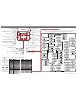
DECODER TERMINAL DESCRIPTIONS
Negative output or Ground from Power Supply.
AC or DC 12-24 Volt from Power Supply.
Data (white wire from Keypad).
(Electric Latch Control) 5 Amp. Relay operates
momentarily with each correct code entered. This
output can be varied for operating times between 1
and 255 seconds (factory set for 10 seconds).
A. Use CM and NO for fail/secure operation.
ie. power applied to unlock latch.
B. Use CM and NC for fail/safe operation.
ie. power removed to unlock latch.
A normally closed input to GND, goes open circuit
when the door is open. The DOOR input is used to
detect when the door has been opened for use by
the door forced open, DOTL and automatic re-lock
functions. The automatic re-lock function turns the
ELC output off 1 second after the door opens,
allowing the door to automatically re-lock when
closed. Note: If the DOOR input is to be used it
must be enabled via Memory 6.
(Door Open Too Long) open collector output
operates when the door has been left open for
longer than the programmed DOTL time or when
the door has been forced open. See
DOOR OPEN
TOO LONG
and
DOOR FORCED OPEN
DETECTION
sections. The DOTL output is
capable of sinking up to 1 Amp.
A normally open or normally closed input to GND.
See
SELECT EGRESS SWITCH TYPE
section.
When this input is activated the ELC output will
turn on and remain on until the input is removed.
Once the EGRESS input has been removed, the
ELC output will continue to operate for the
programmed momentary time and the automatic
re-lock and DOTL functions are also enabled.
OPERATING MODE RULES
1/ 1 beep = successful code (ELC output turned on).
2/ 2 beeps = successful code (ELC output turned off).
3/ 5 beeps = management code entered.
4/ a long beep = a non existent code.
a pause then a long beep = 5 unsuccessful “tries”.
(System is locked out for 1 minute, if enabled in mem 5).
The
and Memory number are NOT required in the
OPERATE mode.
5/ Cancel a wrong entry with
, then re-try.
THE MEMORIES
Memory 0
Memory 1
Memory 2
Memory 3
Memory 4
Toggle
operation user
codes.
Momentary
operation user
codes.
Selects
EGRESS
switch type.
Enable/disable
door forced
open detection.
Door Open
Too Long
time.
Memory 5
Memory 6
Memory 7
Memory 8
Memory 9
Enable/disable
1 minute
lockout.
Enable/disable
Door input for
reed switch.
Use two
codes to
operate ELC.
ELC relay
operate
time.
Management
code.
BASIC SETUP SEQUENCE
1/ Select EGRESS switch type (Currently N/O). [Memory 2]
2/ Set ELC OPERATE TIME (Currently 10 seconds).
[Memory 8]
3/ Enable/Disable DOOR INPUT (Currently disabled).
[Memory 6]
4/ Set Door Open Too Long time (Currently 60 seconds).
[Memory 4]
5/ Enable/Disable DOOR FORCED OPEN DETECTION
(Currently enabled). [Memory 3]
6/
Enable/Disable 1 MINUTE LOCKOUT (Currently
disabled). [Memory 5]
7/
Enable/Disable USE TWO MOMENTARY CODES
(Currently disabled). [Memory 7]
8/ Program MANAGEMENT CODE. [Memory 9]
9/ Program USER CODES. [Memory 1 & Memory 0]
NOTE: Use the Program Link for steps 1 to 8 above (and
step 9 if the management code is not used).
Remove link when finished.
“Series 3”
ELC
GND
AC-DC
DTA
IMPORTANT!
DOOR
DOTL
EGRESS
Enter