PR 3186, Manual
PR 3186 User Manual is an essential guide crafted to simplify the setup and usage process of our product. This comprehensive manual is available for instant download, completely free of charge, from our website manualshive.com. Obtain insightful instructions and maximize your product's potential with our user-friendly manual.
Share
Download


Reviews:
No comments
Related manuals for 3186

CD100
Brand: PANDROL Pages: 36

B100
Brand: Eastwood Pages: 20

BMK1800
Brand: ASAHI Pages: 9

HDC 40/16
Brand: Kärcher Pages: 396

Sibo SZB SE 33U
Brand: Elektro-Automatik Pages: 16

LT40 DH
Brand: Wood-mizer Pages: 133

AutoJet AccuCoat HD15
Brand: Spraying Systems Co Pages: 18

ARW-RH
Brand: Anywire Pages: 6

W-2416Z
Brand: KAKA Industrial Pages: 16
YRPRO YRA302TSB.GX120
Brand: Youngman Richardson & Co Pages: 8

GBAC ROTO BONDER
Brand: Duro Dyne Pages: 12
5500S
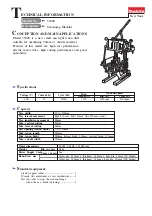
Brand: Makita Pages: 2

SIMATIC IPC
Brand: Siemens Pages: 22

SIMATIC Field PG M4
Brand: Siemens Pages: 22

SIMATIC 6AV7675-1RB00-0AA0
Brand: Siemens Pages: 26

SBMIQR
Brand: Siemens Pages: 4

SIMATIC HMI IPC577C
Brand: Siemens Pages: 36

CP 1625
Brand: Siemens Pages: 31


