FOR YOUR SAFETY
READ AND UNDERSTAND THE ENTIRE MANUAL BEFORE OPERATING
MACHINE
Both model number and serial number may be found on the main label.
You should record both of them in a safe place for future use.
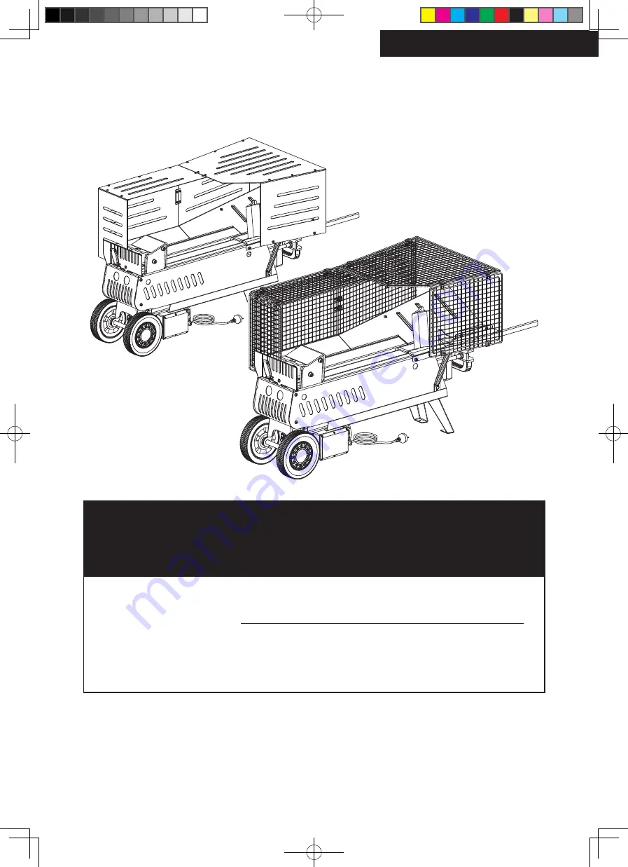
Hydraulic Log Splitter
Operator's Manual
Save This Manual for Future Reference
Original Instruction
MODEL NUMBER :
65575
SERIAL NUMBER
:
65575UK00M111.indd 1
2019/8/30 11:52:28