background image


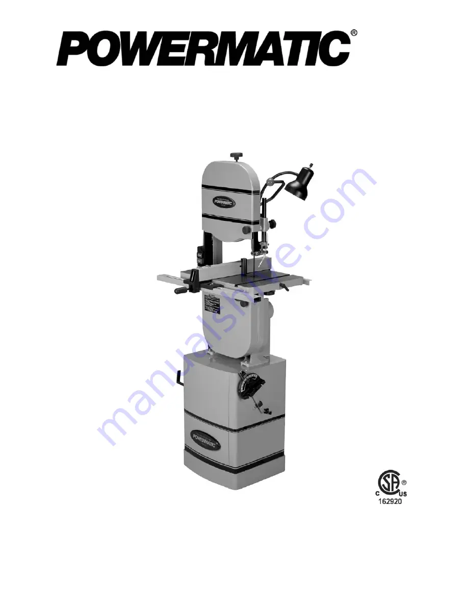
Operating Instructions and Parts Manual 

14” Woodworking Band Saw 

Model PWBS-14CS 


WALTER MEIER (Manufacturing) Inc. 

427 New Sanford Rd. 
LaVergne, TN 37086 

Part No. M-1791216


Ph.: 800-274-6848 

Revision F


07/2013 

www.powermatic.com 

Copyright © 2013 Walter Meier (Manufacturing) Inc. 

This .pdf document is bookmarked

Summary of Contents for 1791216K

Page 1: ...rking Band Saw Model PWBS 14CS WALTER MEIER Manufacturing Inc 427 New Sanford Rd LaVergne TN 37086 Part No M 1791216 Ph 800 274 6848 Revision F 07 2013 www powermatic com Copyright 2013 Walter Meier M...

Page 2: ...ination postage prepaid to a location designated by us For the name of the location nearest you please call 1 800 274 6848 You must provide proof of initial purchase date and an explanation of the com...

Page 3: ...wer Nozzle 18 Work Lamp 18 Installing Quick Tension Lever 19 Stand Attachments 19 Dust Collection 19 Riser Block Accessory 19 Adjustments 20 Tilting the Table 20 Adjusting 90 Table Stop 20 Table Align...

Page 4: ...s List Closed Stand Assembly 40 Closed Stand Assembly 41 Parts List Fence and Rail Assembly 42 Fence and Rail Assembly 43 Parts List Table and Trunnion Assembly 44 Parts List Miter Gauge Assembly 45 P...

Page 5: ...ated lumber Your risk of exposure varies depending on how often you do this type of work To reduce your exposure to these chemicals work in a well ventilated area and work with approved safety equipme...

Page 6: ...on the machine Serious injury could occur if the machine tips over 33 Never leave the machine running unattended Turn the power off and do not leave the machine until it comes to a complete stop 34 Re...

Page 7: ...LxW in 15 x 5 1 2 Blade Speed SFPM 3000 Table Tilt deg 45 Right 10 Left Table Height from Floor in 44 Dust Chute Outside Diameter in 4 Minimum Dust Collection CFM Required 350 Motor TEFC 1 5HP 1PH 115...

Page 8: ...immediately It is recommended that the PWBS 14CS Band Saw when operated at 115 volts be connected to a grounded and dedicated 30 amp circuit with circuit breaker or time delay fuse When operated at 2...

Page 9: ...are not sure have a registered electrician check the receptacle Make sure the lamp bulb is rated 220V when using 230V power for the band saw Figure 4 Figure 5 Figure 6 Figure 7 Extension Cords If an...

Page 10: ...rt F 1 level board G 1 miter gauge H 1 main table J 1 extension table K 1 drive belt L 1 quick tension lever M 1 owner s manual not shown 1 warranty card not shown 2 Hardware packages as follows Hardw...

Page 11: ...1 resaw pin HP4 A 1 resaw pin knob HP4 B 1 fence rear hook HP4 C 2 hex nuts 1 4 HP4 D 1 flat washer 1 4 HP4 E 1 lock washer 1 4 HP4 F 1 sliding pad HP4 G 4 hex cap screws 5 16 x3 4 HP4 H 4 lock washer...

Page 12: ...source before any assembly procedures Mounting Band Saw to Stand Refer to Figures 15 and 16 1 Remove loose items from inside of stand 2 Place stand upright on a level surface If desired the stand can...

Page 13: ...pulley in or out until both pulleys lie in a straight plane Tighten set screw 3 Open the lower door and loosen the four hex nuts on the motor plate an equal amount with a 1 2 wrench see Figure 18 Lif...

Page 14: ...place the level board on them as shown Align the four innermost holes of the level board with the spacers and insert four M8x65 socket head cap screws HP2 H Firmly tighten these screws down into the b...

Page 15: ...rews 5 Adjust the gap between the extension table and the main table This gap can be easily set by using the provided L spacers HP2 J Figure 24 Place the L spacers between the tables as shown and nudg...

Page 16: ...h the fence and rear hook HP4 C Secure in place using a 1 4 flat washer HP4 E 1 4 lock washer HP4 F and a 1 4 hex nut HP4 D The rear hook should be adjusted so that it overlaps the rear rail by approx...

Page 17: ...t aligns with the blade front to back as follows 6 Move the fence so that it just contacts the blade without bending it and lock the fence to the guide rail 7 Check that the fence is aligned with the...

Page 18: ...or Figure 33 Use a lighter or match to briefly heat the end of the hose so that it will slip over the nozzle As it cools it will form a tight seal over the nozzle 2 Attach the plate HP1 A to the blade...

Page 19: ...ts HP3 E and two M8 flanged hex nuts HP3 F The rip fence can be stored in these hooks when not in use Dust Collection Refer to Figure 38 The use of a dust collection system not provided is strongly ad...

Page 20: ...is 90 degrees to the blade Make sure the table insert is level with the table surface to ensure an accurate reading 4 If an adjustment is necessary tilt the table out of the way and tighten the table...

Page 21: ...to back 5 Tighten trunnion screws NOTE After this adjustment the alignment of fence to blade may need to be re checked See Aligning Fence to Blade on page 17 Installing Blades Unplug the machine from...

Page 22: ...nsion and Blade Tracking Blade Tension Refer to Figure 43 1 Disconnect machine from power source 2 Place tension lever in full tension position see Figure 42 3 Turn blade tension knob Figure 43 clockw...

Page 23: ...to shift to one side or the other of the wheel loosen wing nut Figure 45 5 If the blade is tracking toward the front edge of the wheel rotate the tracking knob clockwise the upper wheel will tilt tow...

Page 24: ...ve the guide wheels about 0 004 from the blade A quick way to set this distance is to place a crisp dollar bill which is approximately 004 thick between guide wheel and blade and move the guide until...

Page 25: ...inished Miter Gauge Refer to Figures 51 52 A miter gauge is provided for crosscutting Slide the miter gauge into the T slot from the edge of the table To use the miter gauge loosen the handle and rota...

Page 26: ...guide post clean occasionally apply a light coat of oil Oil any pins shafts and joints Do not get oil on pulleys or belts Bearings on the band saw are sealed for life and do not require attention Che...

Page 27: ...ill cut slowly but more smoothly A coarse pitch fewer teeth per inch will cut faster but more roughly As a rule of thumb the thicker the workpiece the coarser will be the blade pitch If you have to cu...

Page 28: ...or carbide tips Because of the importance of blade selection it is recommended that you use the blade selection guide on page 35 Also listening to experienced band saw users will provide valuable info...

Page 29: ...orkpiece slowly into the blade while also keeping it pressed against the fence or held against the miter gauge Do not force the workpiece into the blade Some further operating tips Make relief cuts wh...

Page 30: ...ustments Inspect the band saw for the following Fence is not parallel to miter slot and blade Blade is not tensioned correctly Blade is dull Teeth have too much set on one side of the blade Workpiece...

Page 31: ...em If voltage between starter and motor is incorrect you have a starter problem If voltage between starter and motor is correct you have a motor problem Motor overheated Clean motor of dust or debris...

Page 32: ...urface finish on workpiece is rough Saw blade speed is too low Increase speed Saw blade pitch is too coarse Change to finer pitch blade Saw blade cutting inaccurately Cuts are not straight Blade mount...

Page 33: ...de thickness not suitable for band wheel diameter Replace with proper thickness blade Blade sharpened incorrectly becomes overheated Sharpen blade properly or replace Band wheels have become misaligne...

Page 34: ...blade annealed or eliminate brittle part and weld correctly Blade cooled too rapidly after welding Have blade annealed or eliminate brittle part and weld correctly Premature dulling of saw teeth Blade...

Page 35: ...ually measure the smallest cutting radius required and locate this radius in inches on the chart at the right Follow the curve to where the approximate blade width is specified If a radius falls betwe...

Page 36: ...9 Wheel Tire 2 20 TS 1550061 Flat Washer M8 2 21 PWBS14 121 Hex Cap Screw M8 x 25 LH 1 22 PWBS14 122 Upper Wheel 1 23 PWBS14 123 Retaining Ring R35 2 24 BB 6202ZZ Ball Bearing 6202ZZ 2 25 PWBS14 125 L...

Page 37: ...1 111 PWBS14 211A Upper Wheel Sliding Bracket serial 71210381 and higher 1 PWBS14 211 Upper Wheel Sliding Bracket serial 71210380 and lower 1 TS 1522021 Socket Set Screw M5 x 8 2 112 PWBS14 212 1A Upp...

Page 38: ...older 1 145 PWBS14 245 Nut 1 146 PWBS14 251 5 Pan Head Flanged Screw M5 x 8 2 147 PWBS14 247 Flexible Pipe 1 148 PWBS14 248 Cord Clamp 1 149 PWBS14 249 Jet Head 1 150 TS 1533042 Phillips Pan Head Mach...

Page 39: ...39 Body Assembly...

Page 40: ...illips Machine Screw M4 x 8 1 9 TS 1550021 Flat Washer M4 2 10 PWBS14 310 Socket Cap Bolt M4 x 40 2 11 PWBS14 311 Sponge 2 12 PWBS14 312 Door 1 13 PWBS14 313 Door Latch Assembly 1 14 PWBS14 314 Washer...

Page 41: ...41 Closed Stand Assembly...

Page 42: ...440 Screw 3 16 x 1 4 1 12 JWBS14 F12 Fence 1 13 JWBS18 439 Flat Washer 5 16 4 14 TS 0720081 Lock Washer 5 16 4 15 TS 0081031 Hex Cap Screw 5 16 x 3 4 4 16 PWBS14 F16 Knob 1 17 JWBS18 444 Sliding Pad...

Page 43: ...43 Fence and Rail Assembly...

Page 44: ...6 TS 1491081 Hex Cap Screw M10 x 50 2 47 PWBS14 147 Hex Head Flange Bolt 6 48 TS 1490151 Hex Cap Screw M8 x 80 1 49 TS 1540061 Hex Nut M8 1 50 PWBS14 150 Trunnion Clamp Shoe 1 51 PWBS14 151 Knob M10 2...

Page 45: ...tems 1 thru 9 1 1 PWBS14 251 1 Guide Bar 1 2 PWBS14 251 2 Guide Piece 1 3 PWBS14 251 3 Counter Sunk Bolt M6 x 6 1 4 PWBS14 251 4 Pointer 1 5 PWBS14 251 5 Pan Head Flanged Screw M5 x 8 1 6 PWBS14 251 6...

Page 46: ...rew M5 x 12 2 93 11 PWBS14 193 11A Spring Pin 3 x 16 mm 1 93 12 PWBS14 193 12 Spring Pin 1 93 13 PWBS14 193 13A Countersunk Head Bolt 5 16 x 1 1 4 1 94 PWBS14 194A Countersunk Head Bolt 1 4 x 1 1 4 2...

Page 47: ...47 Electrical Connections for PWBS 14CS...

Page 48: ...48 WALTER MEIER Manufacturing Inc 427 New Sanford Rd LaVergne TN 37086 Phone 800 274 6848 www powermatic com www waltermeier com...

Reviews: