1
PWX240
2
PWX9513
3
PWX20008
4
PRX20005
5A+B PWXVS
6
PWX9472
7
PWX20020
8
PWX9470 (BETON)
8
PWX9471 (LINER)
9
PWX20021
10
PRX9120
11
PWX20007
12
PRX20018
ATTENTION : NE PAS FAIRE FONCTIONNER
LES PROJECTEURS HORS DE L'EAU
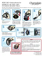
Projecteur Incandescence - série 8145x
CARACTERISTIQUES TECHNIQUES
Le projecteur doit éclairer dans le sens opposé à la maison ou à la terrasse
pour ne pas gêner par un éclairage trop violent.
Le projecteur doit être positionné à 60 cm. au maximum sous la margelle depuis
l'axe de l'ampoule. La niche du projecteur est pourvue de deux sorties 3/4". La
sortie arrière est généralement utilisée pour les piscines maçonnées et la sortie
verticale pour les piscines panneau.
300 W - 12 V - AC / Utiliser un transformateur de sécurité avec un
secondaire > ou égal à 300 VA sous 12 V
STRUCTURE MACONNÉE LINER
.
Sceller la niche du projecteur dans la maçonnerie. Finir l’enduit à fleur
de la face avant, en respectant l’orientation haute de la niche. Condamner la
sortie non utilisée avec le bouchon.
.
Poser le joint sur la face avant de la niche du projecteur.
.
Poser le joint sur la bride de la niche du projecteur.
.
Fixer la bride d'étanchéité après la pose du liner.
.
Découper le liner
STRUCTURE MACONNÉE SANS LINER
.
Sceller la niche du projecteur dans la maçonnerie, la partie avant
en retrait pour la réalisation de l'enduit fini ou du carrelage
.
.
Réaliser l’étanchéité de la gaine du cable, et la pose de l’optique
projecteur identique au projecteur liner.
INSTALLATION DU PROJECTEUR
.
Passer le cable de l'optique du projecteur à l’intérieur du presse étoupe.
Attention au positionnement de la garniture du presse étoupe.
.
Aiguiller le cable de l'optique du projecteur dans la gaine jusqu'à
la boite de connexion.
.
Réaliser l'étanchéité du cable avec le presse étoupe. Attention respecter le
positionnement de la garniture de ce presse étoupe. (l’extrémité avec angle
30° est positionnée en fond de corps de presse étoupe).
.
Présenter l'optique devant la niche en y enroulant le supplément
de cable.
.
Encastrer l'optique du projecteur dans la niche en postionnant
les griffes dans les stries.
MAINTENANCE DU PRODUIT
Le remplacement de pièces doit être effectué avec des pièces d’origines.
Lors d’un changement d’ampoule et/ou du câble, il est préconisé de changer la
totalité des pièces assurant l’étanchéité. Type de lampe utilisé : PAR 56 en cas de
nécessité de changement de la lampe, utiliser la pièce d’origine.
Si le cordon d’alimentation ou la gaine est endommagé, il doit être remplacé par
le fabricant, un Centre Service Agréé ou un technicien qualifié afin d’éviter tout
accident.
BOITE DE CONNEXION
(non fournie)
.
Raccorder la gaine du projecteur à la sortie 3/4“ située sur le fond de la boîte
de connexion.
.
Les sorties des côtés permettant le passage des cables d’alimentation
électrique.
RACCORDEMENT DANS LA BOITE DE CONNEXION (non fournie)
Préconisation de raccordement : raccorder dans la boite de connexion (non fournie)
IPX5, l’extrémité du câble à l’alimentation venant du local technique, utiliser les blocs
de jonctions fournis avec les boites de connexion pour raccorder le projecteur à
l’alimentation en torsadant les fils et serrant bien les vis des bornes de jonctions.
.
Le fabricant ne pourra être tenu pour responsable d'un dommage direct
ou indirect provenant d'une utilisation ou installation incorrecte du produit.
.
Informations indicatives, représentations, photos et schémas
non contractuels.
WARNING! DO NOT ATTEMPT TO USE
THESE LIGHTS OUT OF WATER
Incandescent underwater light - serial 8145x
TECHNICAL CHARACTERISTICS
Point the projector away from the house or terrace, so as not to create an
excessively bright illumination.
The projector should not be positioned more than 60 cm under the coping, as
measured from the centre of the bulb. The projector’s niche incorporates two 3/4’’
outlets. The rear outlet is generally used for masonry swimming pools, while the
vertical outlet is primarily intended for swimming pools built from panels.
300 W - 12 V - AC / Use a safety transformer with an output greater than or
equal to 300 VA at 12 V.
LINER MASONRY STRUCTURE
.
Seal the projector’s niche into the masonry, making sure that you position
it the right way up. Fit the plug in the unused outlet. Take necessary steps
to ensure that you can subsequently apply rendering around the front
panel.
.
Fit the seal on the front panel of the projector’s niche.
.
Fit the seal on the flange of the projector’s niche.
.
Secure the sealing flange after installing the liner.
.
Cut the liner
MASONRY STRUCTURE WITHOUT LINER
.
Seal the niche of the projector into the masonry; the front part should be
recessed, so that finishing rendering or tiling can be applied
subsequently.
.
Proceed with sealing the flexible conduit and cable, and install the lighting
unit of the projector in the same way as for the vinyl light.
INSTALLATION OF INCANDESCENT LIGHT
.
Push the projector’s lighting unit cable through the cable gland. Warning,
respect the positioning of the gaskat of the bushing.
.
Thread the cable of the projector’s lighting unit through the
flexible conduit up to the connection box.
.
Seal the cable gland around the cable. Warning, respect the positioning of the
gasket of the bushing. (the end with angle 30° is positioned in bottom of body).
.
Place the lens in front of its housing rolling up any extra cable.
.
Fit the projector’s lighting unit into the niche, positioning the
claws within the striae.
PRODUCT MAINTENANCE
Original components must be used in all replacement operations.
When changing a bulb and/or cable, it is recommended that all components be
changed to avoid compromising the seals. Type of light used : PAR 56, in the
event of necessity changing of the light, to use original part.
If the external flexible cable or cord of this luminaire is damaged, it shall be
exclusively replaced by the manufacturer or his service agent or a similar qualified
person in order to avoid a hazard.
CONNECTION BOX (not provided)
.
Connect the light flexible conduit to the 3/4’’ outlet located on the
bottom of the connection box.
.
The outlets on the sides allow throughway for electrical power
cables.
CONNECTION WITHIN THE JUNCTION BOX (not provided)
Recommendation of connection : to connect in the junction box (not available)
IP X 5, the end of the cable for electrical power supply coming from the technical
box, use the connector blocks provided with the juction box to connect the
spotlight to the power supply by twisting the wires and ensuring that the terminal
screws are well tightened.
.
The manufacturer can not be considered as responsible for a direct or
indirect damage resulting from an use or an incorrect installation of the
product.
.
Indicative information, not contractual photos and schema.
Informations indicatives, représentations “photos & schémas” non contractuelles.