background image

Please read and save these instructions. Read carefully before attempting to assemble, install, operate or maintain the product described.
Protect yourself and others by observing all safety information. Failure to comply with instructions could result in personal injury and/or
property damage! Retain instructions for future reference.

Powerex • 150 Production Drive • Harrison, OH  45030 • USA
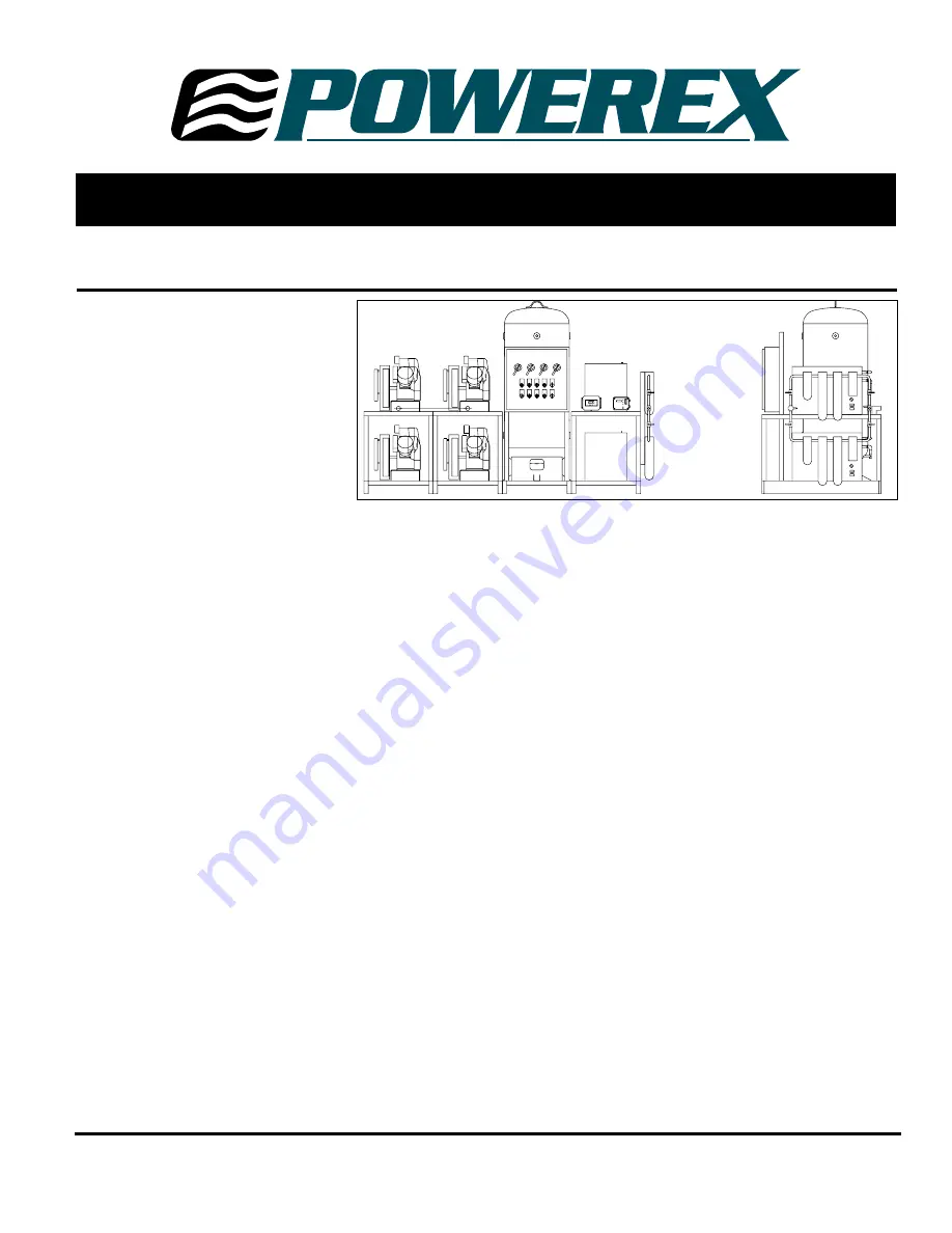
Description

The Powerex medical system package is
designed to provide medical breathing
air for hospital and medical institutes.
This system meets NFPA 99
requirements for Level 1 breathing air.

OILLESS OPT/OPS COMPRESSOR

The Powerex oilless reciprocating air
compressor has advanced compressor
technology through the development
of  a completely oilless compressor. The
Powerex reciprocating compressor is
provided in duplex, triplex or quadplex
configurations with head unloaders to
provide start, stop or continuous
operation. Composite piston
technology and continuously
lubricating bearings provide oil-free air
reliability for years to come.

RECEIVER TANK

The ASME, National Board registered
air receiver is provided in sizes from
120 to 240 gallons. Each receiver is
rated at 200 PSIG working pressure.
Receivers are provided with sight glass
and moisture drain (manual or
automatic).

CONTROL PANEL

The NEMA 12 control panel is provided
in duplex, triplex or quadplex
configurations and meets NFPA 99
requirements for medical air. Primary
voltage is protected by fusing or circuit
breaker. Control transformer power is
110 volts and protected by secondary
fusing. Pressure control switches signal
the compressors on and off cycle and
signal lag compressor(s) to come on if
air demand increases. A lag, lag
pressure switch or transducer signals a
light and audible alarm warning of a
low pressure condition which is factory
set at 40 PSIG. An acknowledge button
is provided for start condition and
maintenance. The adjustable timer
alternator cycles each compressor so
equal run time is maintained. This
alternator is factory set to alternate
the compressors every 10 minutes. The
exterior of the control panel is
accessible through the door.  The panel
disconnects on/off/auto switches run
lights, power on lights, run
hourmeters, lag pressure light, high

GENERAL PRODUCT MANUAL 

temperature light and overload reset.
This control panel is UL listed.

DEW POINT MONITOR

The Powerex dew point monitor
provides indication of dew point and
temperature. It’s microprocessor
controlled with user programmable
output range, alarm and calibration.
The NEMA enclosure is protected by a
polymer viewing cover.

CARBON MONOXIDE
MONITOR/ALARM

The carbon monoxide monitor provides
warning to the user of air-supplied
respirators alarming and metering the
presence of carbon monoxide. The
monitor is provided in a NEMA 12
enclosure. In addition to audio/visual
alarm, the meter displays the
concentration of CO in the compressed
air. The meter operates from a 110
VAC supply. Alarm points are set a
10PPM (low) and 20 PPM (high).

AIR COOLED AFTERCOOLER

Four models of beltguard aftercoolers
sized to provide an approach of 20°F.
Constructed of copper tubing and
metal headers for a rugged
construction.

AIR DRYER (REFRIGERATED OR
DESICCANT)

The Powerex air drying system provides
air at 38°F at 100 PSIG for refrigerated
units and -40°F dew point for desiccant
dryer systems. Each system is connected
with bypass capability. 
The refrigerated compressed air
dryer(s) are noncycling, direct
expansion type, using R-22 refrigerant,

IN259200AV  11/00

P

U

R

E


A

I

R


T

E

C

H

N

O

L

O

G

Y

CFC free. A hot gas bypass valve is
provided to maintain 38°F evaporator
temperature. The dryer is self-
regulating for large load swings. Heat
exchangers are made of copper tube
construction and insulated. 
The regenerative desiccant consists of
two (dual) towers filled with desiccant.
Each tower is switched on and off
stream, alternating the air system
stream and then being regenerated.
Dry purge air pulls moisture from the
desiccant and carries the moisture out
of the air.

MEDICAL FILTER SYSTEM

The medical filter system consists of a
duplex series of filters and pressure
regulators. Air enters the system and is
directed to either bank of filets
controlled by ball valve. The first stage
filter removes solids and liquid
particles. The next stage of filters
remove submicronic particles and
aerosols. The third and final filter is
carbon activated to remove unpleasant
odors. Maximum operating temper-
ature is 125°F and maximum pressure is
150 PSIG.

CONDENSATE DRAIN VALVE

A condensate drain valve must be
installed on any tank. This valve
removes liquid that collects during
compressor operation.
Drain liquid from tank daily.

Safety Guidelines

This manual contains information that is
very important to know and understand.
This information is provided for SAFETY
and to PREVENT EQUIPMENT PROBLEMS.

Medical Package System

CAL. PORT

CAL. PORT

ZERO CAL.

ZERO CAL.

ALARM

ALARM

SET

SET

ADJ.

ADJ.

PANADRY

PANADRY

F

DEW/FROST POINT

DEW/FROST POINT

PPM

PPM

AUTO CAL

AUTO CAL

CAUTION

CAUTION

ALARM

ALARM

SAFE

SAFE

FLOW

FLOW

Summary of Contents for Medical Packing System MPD

Page 1: ...ature It s microprocessor controlled with user programmable output range alarm and calibration The NEMA enclosure is protected by a polymer viewing cover CARBON MONOXIDE MONITOR ALARM The carbon monox...

Page 2: ...maximum allowable working pressure 9 Never attempt to adjust ASME safety valve Keep safety valve free from paint and other accumulations Never attempt to repair or modify a tank Welding drilling or a...

Page 3: ...ng is provided and sealed for this portion of installation 5 Locate and attach intake inline air filter to outside source air or header Flex line is provided when attaching intake of compressors to ri...

Page 4: ...e been read and understood before continuing 2 Remove any shipping materials brackets etc 3 Confirm that the electric power source and ground have been firmly connected 4 Be sure all pressure connecti...

Page 5: ...ance schedule relates to the normal operating conditions If the circumstances and load condition are adverse shorten the cycle time and do maintenance accordingly 3 The tension of the V belt should be...

Page 6: ...lity Call 1 888 769 7979 7 Pressure Gauge Consult factory for number 1 8 Auto Tank Drain Electric ACO100100 1 Float ACO100200 1 9 Isolation Mounts Consult factory for parts and availability Call 1 888...

Page 7: ...4 60 CFM MFP 060 362 1 70 CFM MFP 070 382 1 100 CFM MFP 110 382 1 1 4 220 CFM MFP 220 3A2 See Filter System Manual for details and replacement elements 1 2 3 4 Dryer Filter Parts List Ref No Descripti...

Page 8: ...ry to properly filter and purify the air to meet minimal specifica tions for Grade D breathing as described in Compressed Gas Association Commodity Specification G 7 1 1966 OSHA 29 CFR 1910 134 and or...

Page 9: ...TER The hourmeter on the oilless compres sor indicates the actual number of hours the unit has been in operation The hourmeter is also used to deter mine maintenance and service timing An hourmeter mu...

Page 10: ...30 2 3 8 3 3 7 13 4 17 8 18 9 6 4 43 13 8 Bx1 OPT 050 5 11 4 5 3 18 3 21 9 25 9 7 9 43 16 9 Bx2 OPT 100 71 2 10 12 2 6 3 20 0 21 6 29 7 8 4 55 18 3 Bx2 OPT 150 15 12 2 6 3 20 0 21 6 29 7 8 4 55 19 6 B...

Page 11: ...r less Pressure Gauge Inspect Every 2 500 hrs or less Inspect Replace NOTES 1 Inspect and perform maintenance periodically according to maintenance schedule 2 The maintenance schedule relates to the n...

Page 12: ...surface if foreign matter sticks 5 Clean the whole valve set taking care not to damage seat surface and remove dust 6 If viton seals upper and lower reach inspection time replace them Even if its not...

Page 13: ...Replace if it is swollen by scuffing the aluminum cylinder 3 Replace if several vertical scratches are side by side at a narrow distance NOTE Blackish streaks you can feel with your nail or finger ar...

Page 14: ...REASSEMBLE Pay attention to the fit of the piston and wrist pin fit There should be no axial play or looseness in the wrist pin area NOTE Do not separate piston from connecting rod when inspecting pi...

Page 15: ...iston on two stage pumps remove piston and then insert retention sleeve having the same diameter of piston pin or pis ton to small end of connecting rod If not you may drop or lose needles from the be...

Page 16: ...l seal into the small bear ing end horizontally 5 Press the oil seal with a C clamp into the small bearing end 6 Repeat on opposite side 7 Apply a small volume of adhesive at several points 8 Remove t...

Page 17: ...g shaft 3 Bearing at wrist pin Check for breakage of needle bearing and damage of cage DISASSEMBLING CRANKSHAFT SET 1 Disassemble cylinder head cylinder and piston 2 Remove bolts from bearing cap and...

Page 18: ...11 Oilless Reciprocating Air Compressor Pumps Notes...

Page 19: ...12 Oilless Reciprocating Air Compressor Pumps Figure 24 Replacement Parts Illustration for OPS010...

Page 20: ...1 47 O ring 01146550 1 50 Crank shaft 1 51 Flywheel pulley 91201551 1 52 Parallel pin 01271550 1 57 Ball bearing bearing cap 2 62 Hex blot fan flywheel 06992857 1 65 Connecting rod w bearings 1 67 Pi...

Page 21: ...14 Oilless Reciprocating Air Compressor Pumps Figure 25 Replacement Parts Illustration for OPS030...

Page 22: ...ruff key 06600013 1 53 Hex nut 06994016 2 57 Ball bearing bearing cap 1 58 Ball bearing crank case 1 59 Fan 91220560 1 60 Cover fan 91134560 1 61 Hex bolt fan flywheel 06992857 2 64 Liner connecting r...

Page 23: ...16 Oilless Reciprocating Air Compressor Pumps Figure 26 Replacement Parts Illustration for OPT050 197 197...

Page 24: ...Rod Set 1 66 Connecting Rod Set 1 67 Piston Set LP 91903680 1 67 1 Piston Ring LP 91236681 1 68 Piston Set HP 91910670 1 68 1 Piston Ring HP 91930680 2 68 2 Wrist Pin Prepacked 91924680 1 72 Intake F...

Page 25: ...Oilless Reciprocating Air Compressor Pumps 18 Figure 27 Replacement Parts Illustration for OPT100 and OPT150 197 197 171 172...

Page 26: ...0 2 68 2 Wrist pin set prepacked 91924680 91924680 1 72 Intake filter set 91907590 91907690 1 72 1 Intake filter 91353690 91353690 1 78 O ring Intake pipe 06630032 06630032 2 79 Inlet pipe 01407690 01...

Page 27: ...the products in this lit erature accurately however such illustrations and descriptions are for the sole purpose of identification and do not express or imply a warranty that the products are merchan...

Reviews: