PowerBoss Admiral 38C, User Manual
The PowerBoss Admiral 38C user manual is essential for smooth operation and maintenance of this powerful cleaning machine. Easily downloadable for free from our website, it provides comprehensive instructions and troubleshooting tips, ensuring optimal performance. Get your manual today from manualshive.com and unlock the full potential of your Admiral 38C.
Share
Download


Reviews:
No comments
Related manuals for Admiral 38C

BG-AEE
Brand: BZB Gear Pages: 12

ScrubMaster 26C
Brand: Pacific Pages: 22

SCRUBTEC BOOST R4
Brand: Nilfisk-ALTO Pages: 124

Convertamatic 260B
Brand: Nilfisk-Advance Pages: 58

MX 307 H
Brand: Nilfisk-Advance Pages: 72

PREDATOR PRED750
Brand: Abatement Technologies Pages: 21

NZHPH020P
Brand: Nobles Pages: 2
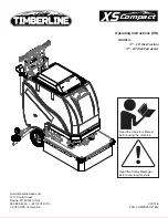
XS Compact 17" Disk Pad Assist
Brand: Timberline Pages: 30

TASKI swingo XP-M
Brand: Sealed Air Pages: 137

HEXA-01
Brand: PureLink Pages: 11

MASTERFORCE
Brand: MASTERBLEND Pages: 30


