CONGRATULATIONS
on your purchase
of a Power-Pole
Signature Series shallow
water anchor featuring C-Monster Control
System. It has been designed, engineered,
and manufactured to provide the best possible
performance and dependability for years of
enjoyment.
Please read all installation instructions carefully.
The information contained here describes the
proper procedures for safely installing your
Power-Pole shallow water anchor.
CAUTION:
Do not use the Power-Pole
shallow water
anchor as your primary anchorage. Never
leave your boat unattended while anchored
solely with the Power-Pole
shallow water anchor.
INSTALLATION MANUAL
Power-Pole
®
Signature Series
Shallow Water Anchor
Installation Instructions
CAUTION:
Read this instruction manual carefully. Become
familiar with the controls and know how to operate the
Power-Pole
shallow water anchor system safely.
US Pat No. 6,041,730
9208 Palm River Road, Suite 303, Tampa, Florida 33619
Phone 813-689-9932 Fax 813-689-8883
www.power-pole.com
Step 1: Choose a Mounting Location
Transom mounting
VeRTICAL POSITIONING
1. Place a straight edge on the bottom of the hull directly
below and centered from the desired mounting
location. The lowest point of the Power-Pole anchor
must be at least 4” above this straight edge.
Note:
If the Power-Pole anchor is mounted lower than
the 4” minimum, the vessel may experience adverse
handling effects. (See Figure #1)
CLeARANCe
1. If the vessel is equipped with trim tabs that measure 9”
or less in length, the standard 4” minimum mounting
height will be sufficient. If the trim tabs are larger than
9”, the Power-Pole anchor will need to be mounted
higher up on the transom to prevent interference.
2. While holding the Power-Pole anchor in place, turn and
tilt the motor as far as possible toward the unit. With
the motor turned toward the unit, manually move the
anchor through its entire range of motion to verify
clearance.
3. Once clearance has been verified on the exterior
portion of the vessel, check for adequate space on the
inside of the transom mounting area. Make sure that
the bolts will not have any obstructions, and that you
will have space to tighten the 5/16” tall brass nuts
D
.
Adapter plate mounting
1. If there is no suitable mounting location on the
transom, your vessel will require an adapter plate. We
offer adapter plates to accommodate a wide variety
of applications. Please contact one of our authorized
dealers or a member of our sales staff for an adapter
plate recommendation:
(813) 689-9932 option 1
2. All adapter plates are accompanied by installation
instructions. Refer to the included instructions while
installing the adapter plate as well as the Power-Pole
anchor. Please contact our technical support team
with any questions:
(813) 689-9932 option 2
J
K
A
B
C
D
E
F
G
H
i
L
M
N
Step 9: Installing the Dash Switch
1. Locate a suitable area with a flat surface to mount
the dash switch.
2. The dash switch must be installed with the slot in the
base facing downward, which can be accomplished
by using the supplied adhesive strip
N
or the (2)
included #6 x 1/2” pan head screws
G
.
3. If using the (2) #6 x 1/2” pan head screws
G
, use a
small slotted screwdriver to remove the dash switch
cover plate. (See Figure #12)
4. While holding the dash switch base in the desired
location, use a fine point marker to inscribe the
intended mounting screw locations.
WARNING:
Before drilling pilot holes for the dash
switch mounting screws, inspect the area beneath
the mounting surface in order to ensure that the
drill bit will not cause any damage.
5. Using the 7/64” drill bit, carefully drill holes in the
previously inscribed location.
6. Fasten the dash switch base to the vessel using a #2
Phillips-head screwdriver and the (2) #6 x 1/2” pan
head screws
G
.
7. With the base installed, ensure that the rubber switch
membrane is seated properly prior to installing the
cover plate. (See Figure #13)
Need help? Contact our Technical Support Team at
813.689.9932 option 2
©2012 all rights reserved. Power-Pole Shallow Water Anchor U.S. Patent No. 6,041,730
4”
Figure 1
Figure 12
Figure 13
L
K
A
B
C
D
E
J
i
F
G
H
M
N
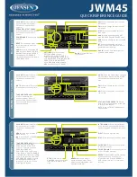
Installation Tools & Hardware
Installation Tools
• 1/2” & 9/16” wrenches
• 1/2” & 9/16” sockets with ratchet
• electric or battery operated drill
• 7/64”, 9/64”, 5/16”, & 11/32” drill bits
• #2 Phillips-head bit or screwdriver
• Small slotted (flat-headed) screwdriver
• Heat gun
• 4’ foot straight edge
• Marine grade sealant
• Fine point marker
• Tape measure
• Wire cutters
• Wire strippers
• Wire terminal crimpers
• Razor tubing cutter or utility razor blade
• Small funnel
Installation Hardware
Qty(4) 5/16” x 3.5” all-thread transom mount bolts
Qty(4) 5/16” neo-bond washers
Qty(4) 5/16” fender washers
Qty(4) 5/16” tall brass nuts
Qty(2) 3/8” x 3/4” bolts
Qty(2) 3/8” neo-bond washers
Qty(2) #6 x 1/2” pan head screws
Qty(4) #10 x 3/4” pan head screws
Qty(1) rubber pump gasket
Qty(2) ring connectors
Qty(2) thru-hull bushings
Qty(3) marine cable ties
Qty(1) 5’ black mesh tubing cover
Qty(1) adhesive strip