


QUESTIONS?
Ask the experts at POSMicro.com.
1.800.241.6264
Live Chat Now
Monday - Friday 6 AM to 5 PM Pacific
Time
BULk DISCOUNTS
FREE SHIPPING*
SE HaBLa
ESpa
ñ
OL
*Free ground shipping to the continental USa on orders over $100.
For Help Call
1.800.241.6264
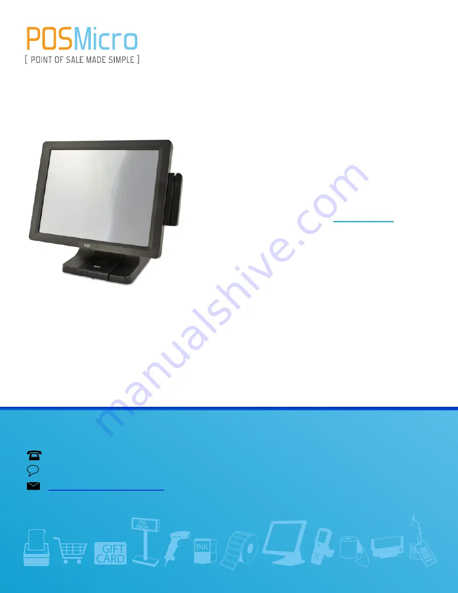
POS-X EVO-TP4 Pro
Manual
More information available at
POSMicro.com


