


QUESTIONS?
Ask the experts at POSMicro.com.
1.800.241.6264
Live Chat Now
Monday - Friday 6 AM to 5 PM Pacific
Time
BULk DISCOUNTS
FREE SHIPPING*
SE HaBLa
ESpa
ñ
OL
*Free ground shipping to the continental USa on orders over $100.
For Help Call
1.800.241.6264
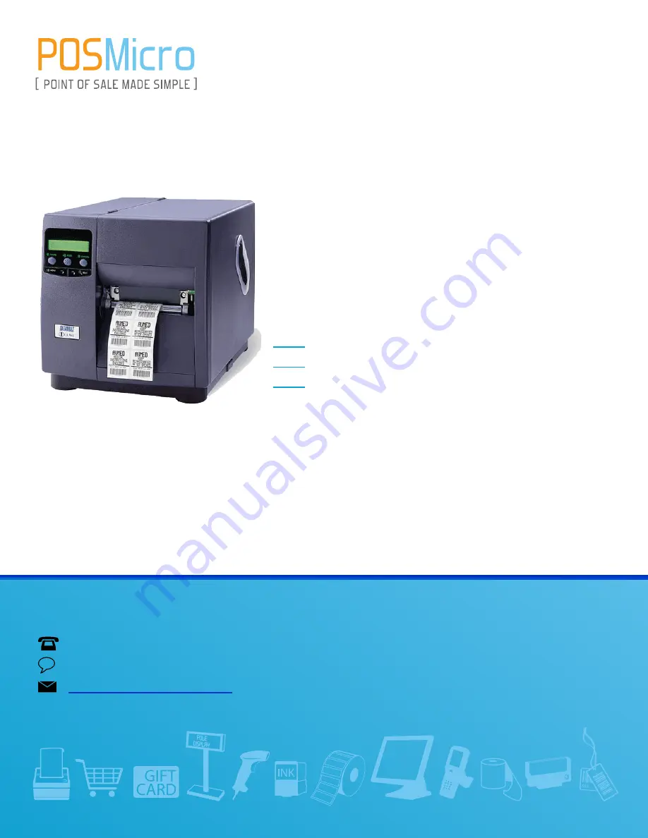
Datamax I Class
Manual
THIS DOWNLOAD APPLIES TO THE FOLLOWING
I4208
I4212
I4308
Summary of Contents for I4208
Page 2: ...Operator s Manual ...
Page 3: ......
Page 7: ......
Page 17: ...6 I Class ...
Page 29: ...18 I Class ...
Page 69: ...58 I Class ...
Page 95: ...84 I Class ...
Page 115: ...104 I Class ...
Page 119: ...108 I Class ...
Page 133: ......


