


Package Contents
HS-6510W/6512W/6514W desktop POS (x 1)
24V/100W Power Adaptor (x 1)
Power cord (x 1)
3-inch wide thermal paper roll (x 1)
Paper separator for 2” thermal paper roll (x 1)
Desktop mounting kit pack for HS-6510/6512 (x 1)
(including 1 desktop mounting bracket,
4 fixing screws, and 4 plastic anchors)
Desktop mounting kit pack for HS-6514 (x 1)
(including 1 bottom plate, 1 desktop mounting
bracket, 4 fixing screws, and 4 plastic anchors)
User manual (x 1)
15680900010 Ver. A0
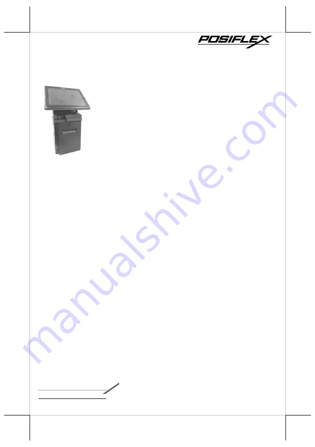
HS-6510W/6512W/6514W
JIVA Desktop POS
User Manual
1


